
Axonometric Drawings
Along with 2D orthographic drawings, it is common for architecture students to also delve into the world of 3D projections. The most common three-dimensional drawings that you will be introduced to during your studies are isometric, axonometric and oblique projections. These can be applied to plans, sections and elevations. Before we jump into the tutorial we’ll be discussing the main principles of what makes a drawing axonometric and then move onto generating it in Rhino.
Axonometric Drawings
Axonometric projections are drawings which follow a rotation of 30,60,90 or 45,90,45 angle sequence. The two different sequences allow us to work with shapes other than simple boxes, for example triangles. These types of drawings can be scaled and used to take measurements from unlike the other two common projection drawings; oblique and isometric. This is because the subject of the projection is never distorted and only a matter of rotation and extrusion. It is helpful to accompany 2D orthographic plans with axonometric drawings since it helps us capture a better understanding of the spaces.
For the tutorial ahead, you will need to be aware of basic rhino modelling skills since the projection drawing will be extracted from a 3D model. If you are unfamiliar with rhino as a software platform, you can read our ‘Getting Started with Rhino 3D’ before proceeding with this post.

1. 3D Model
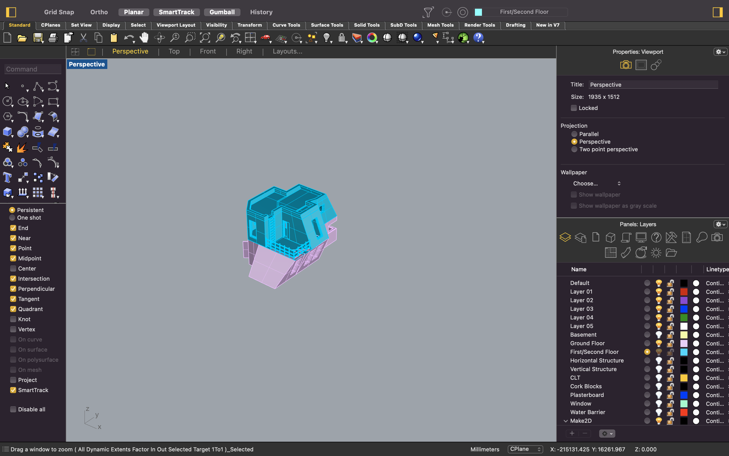
So as mentioned in the introduction above, you will need to have a 3D model in order to computer generate your axonometric drawing. It is also possible to import a 3D model from a different software platform into Rhino 3D as long as they are both compatible with each other. Ideally, you want all your solids, surfaces and other components to be recognised in Rhino 3D so you can experiment with blowing up your axo drawing too.
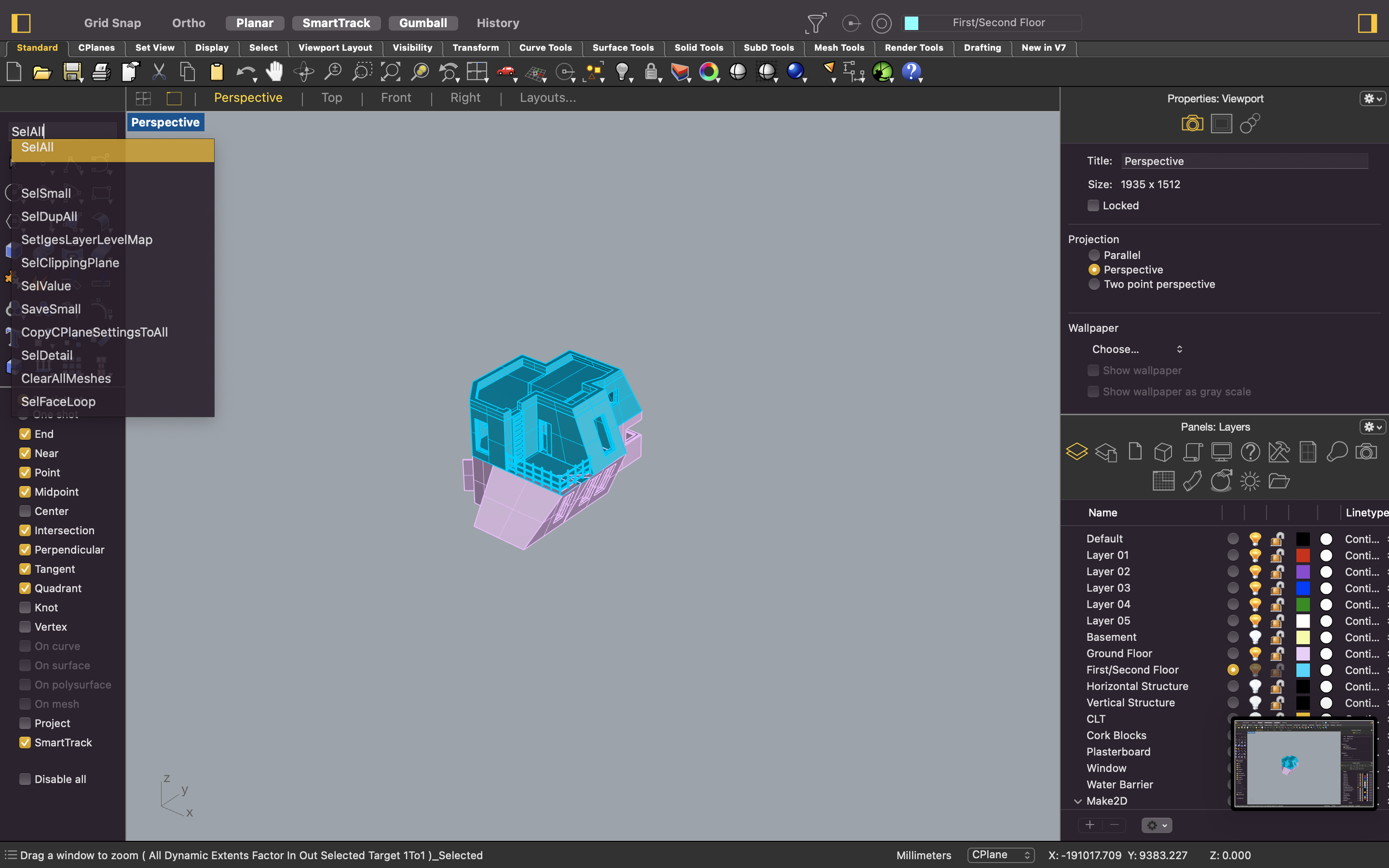
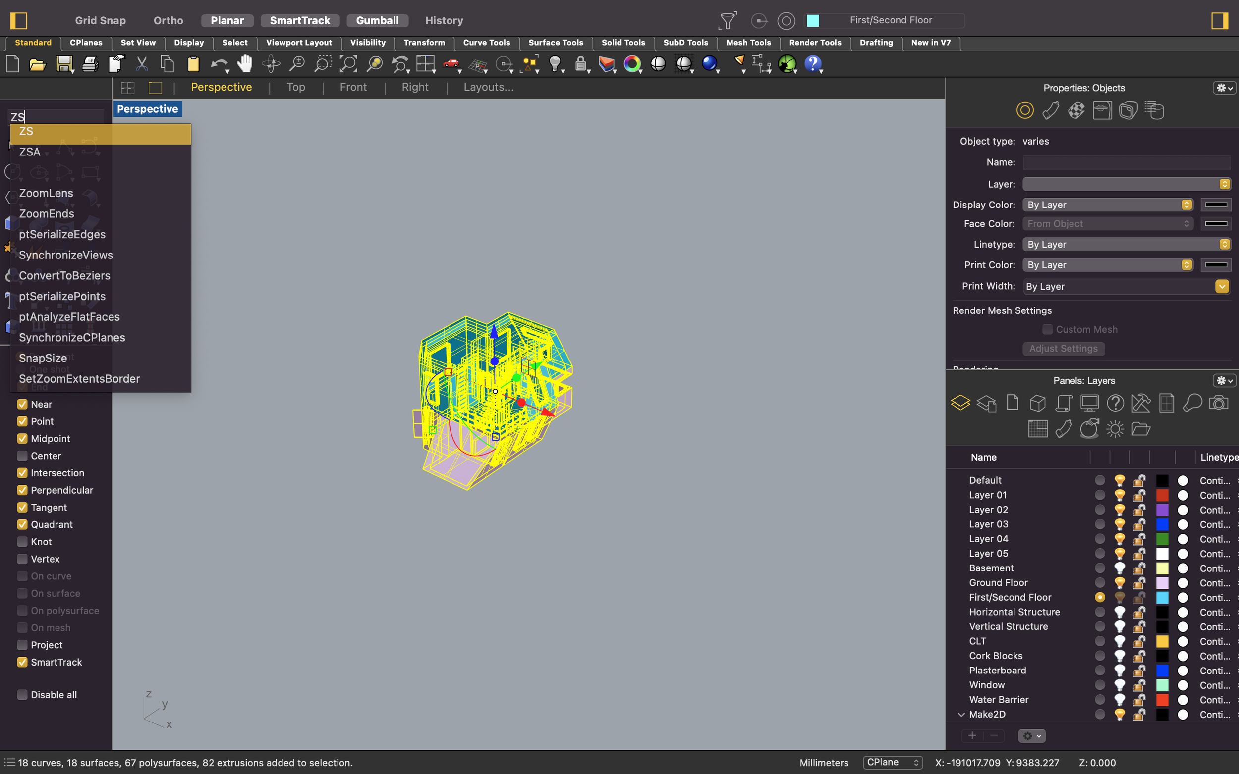
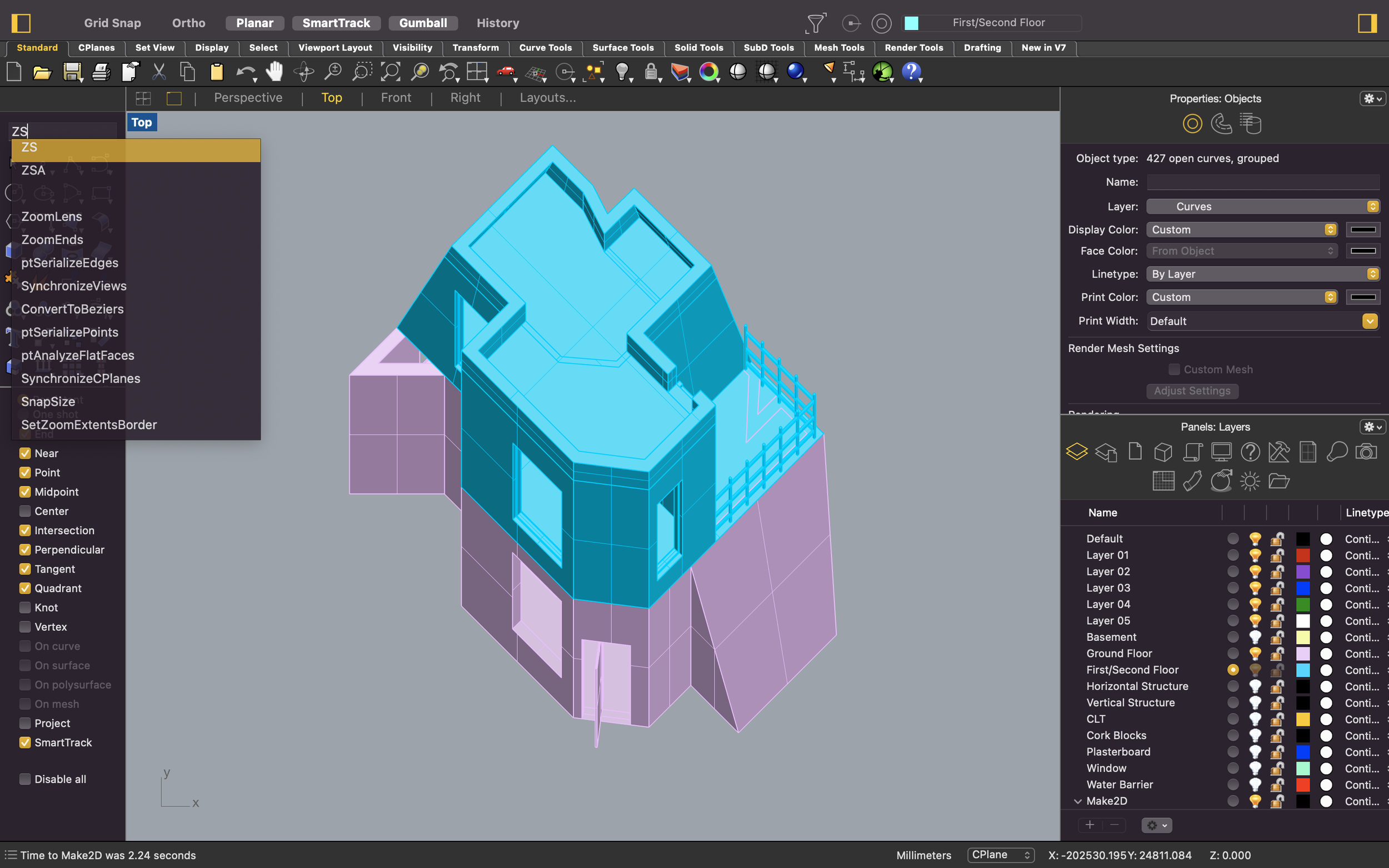
A common command combination that will help with navigating around in Rhino is ‘SelAll’ and ‘ZS’. At times when you copy something into Rhino or import a 3D model, you may struggle to actually find the component in your window. You can simply use ‘SelAll’ which is short for select all and then use ‘ZS’ which stands for zoom into selected. This will automatically zoom into the selected objects in Rhino.
2. Viewports
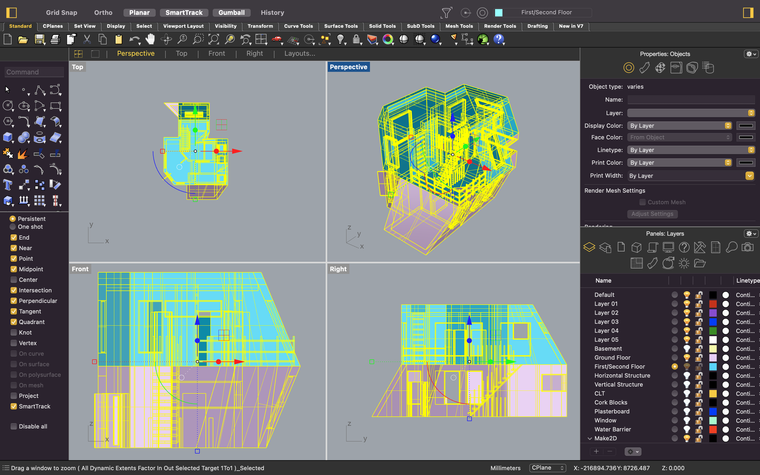
Through this tutorial, we will be working between different viewports. It will be convenient to have all 4 viewports (perspective, top, front and right) up at the same time whilst working with the 3D model. With regards to the axonometric drawing, we will be working in ‘top’ and ‘right’ view.
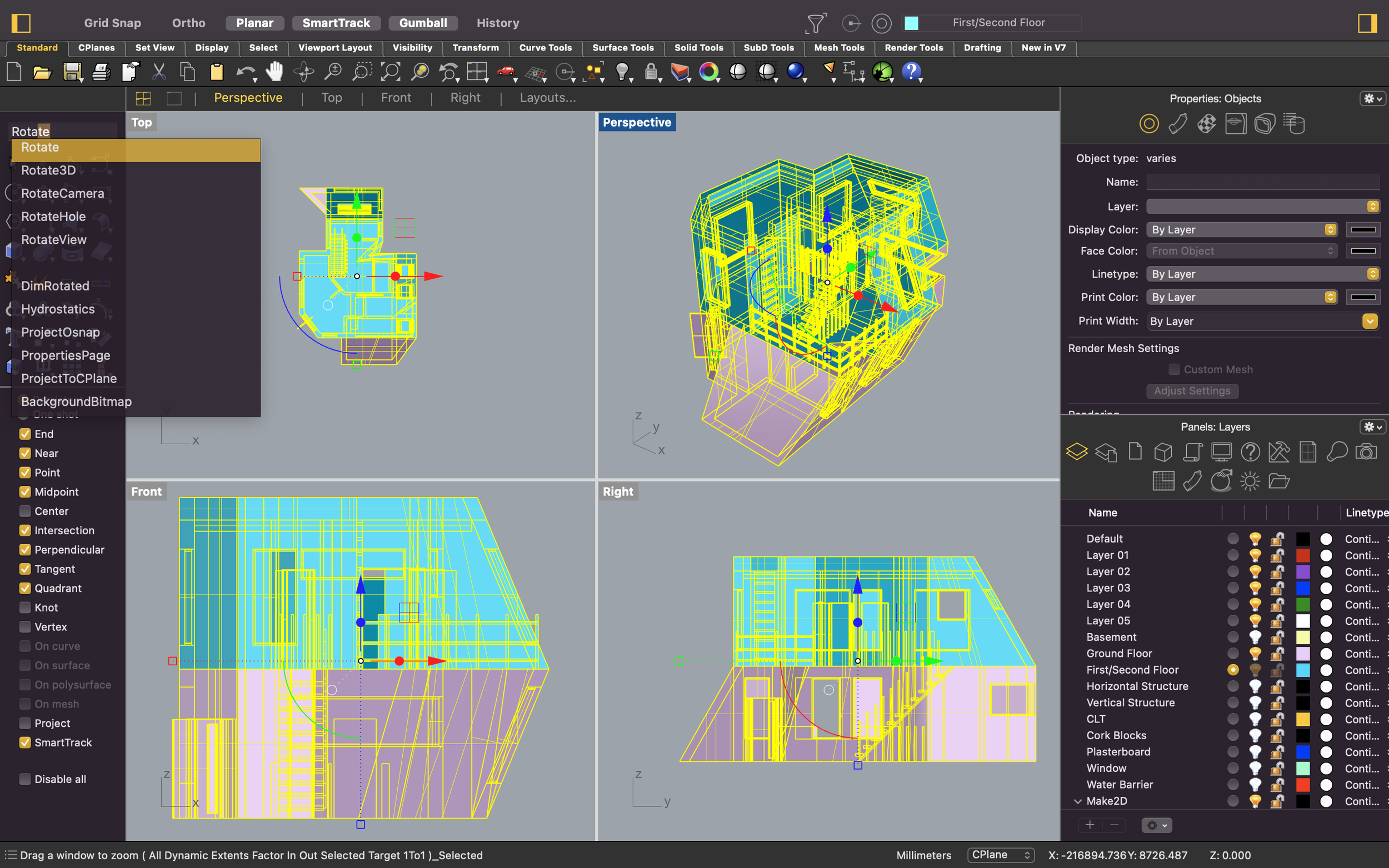
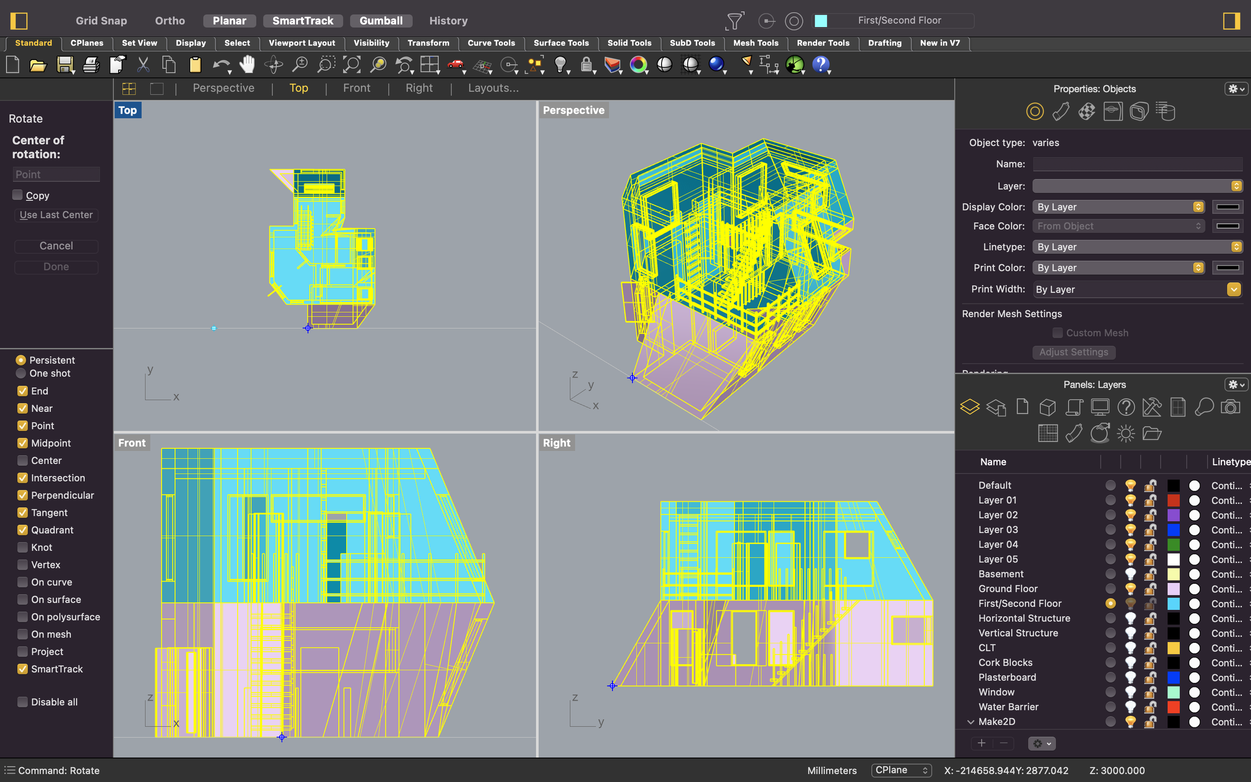
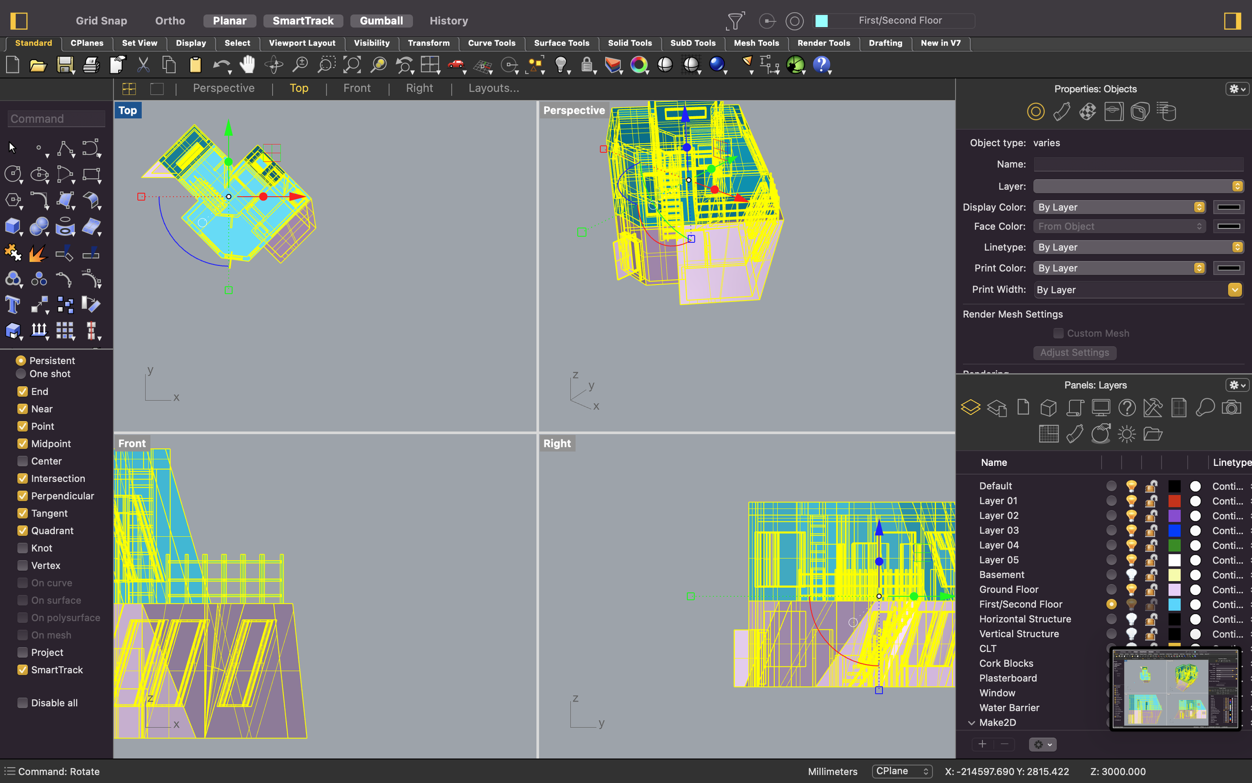
3. Rotate
We mentioned before that axonometric projections have a 30,60,90 or a 45,90,45 angle sequence. In this example we will be following the 45,90,45 sequence. In your ‘Top’ view window, use the ‘Rotate’ tool to rotate your 3D model by 45 degrees as shown in the screenshots below.

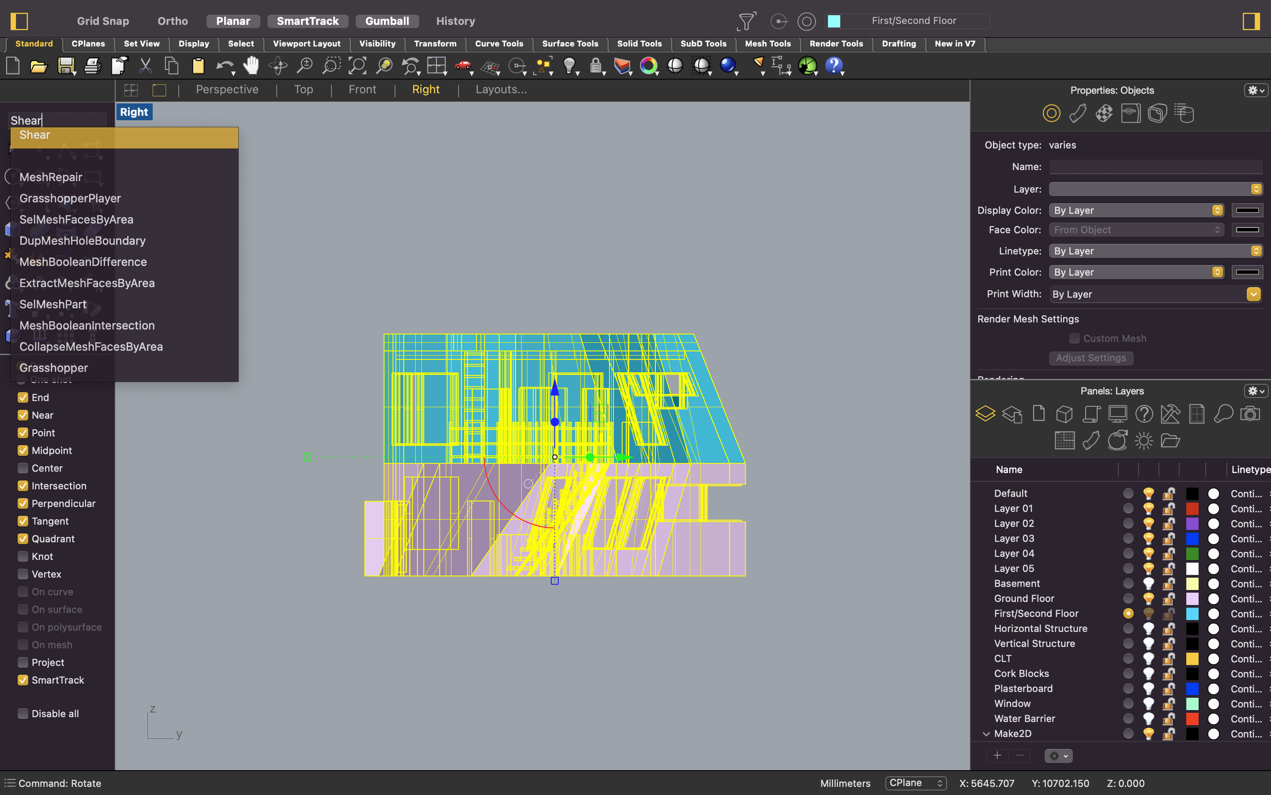
4. Shear
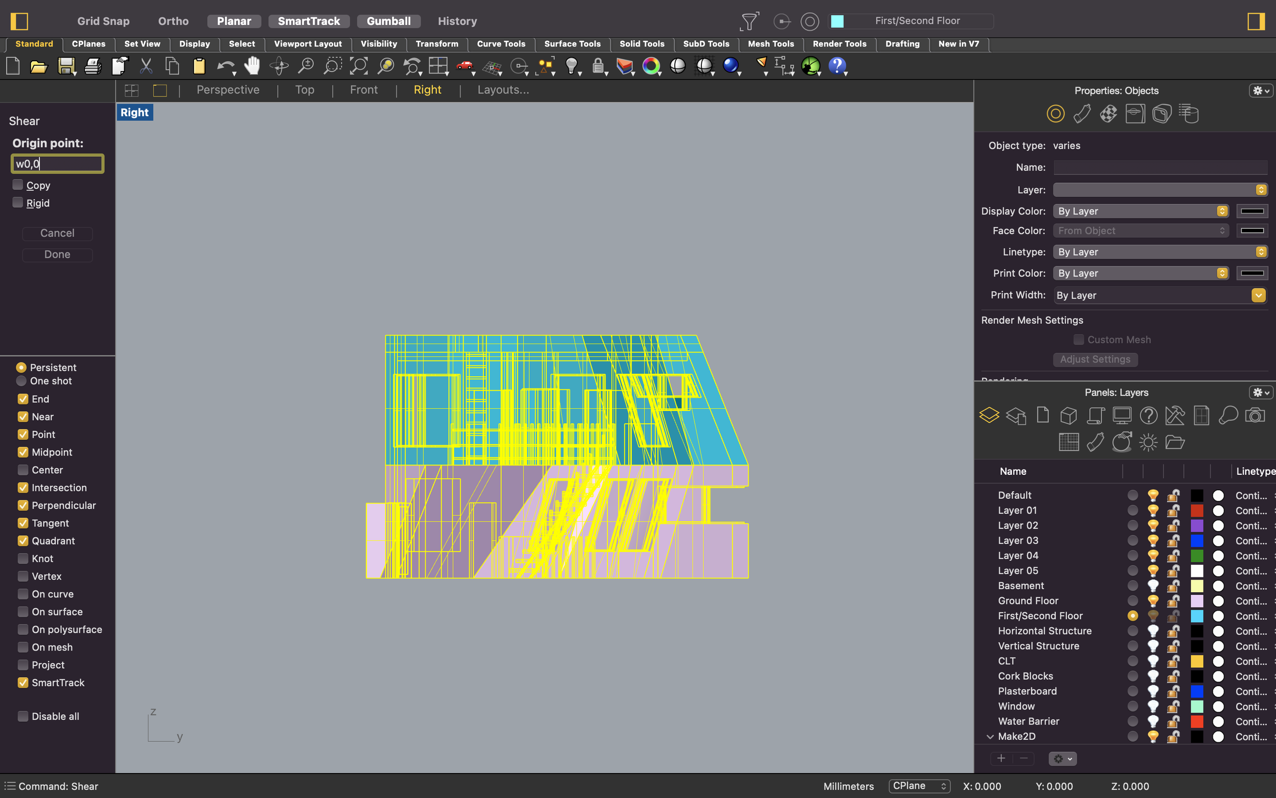
The next couple steps will be done in the ‘Right’ viewport. Double click on your ‘Right’ window in order to zoom into the viewport. We will be using ‘Shear’ in order to create the axonometric projection. Make sure to have your 3D model still selected whilst using the ‘Shear’ tool. If you have deselected, you can always use the ‘SelAll’ command to reselect.
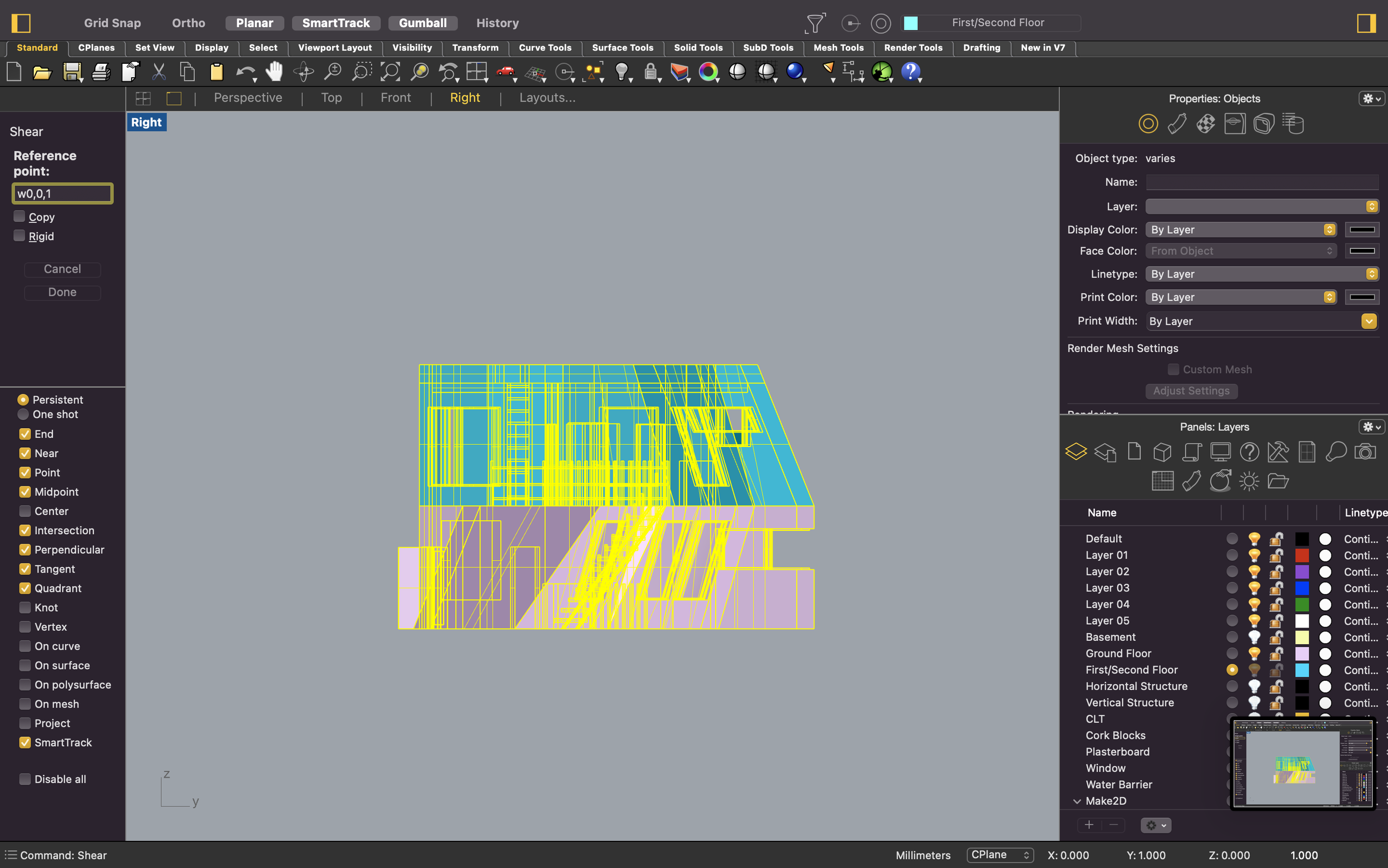
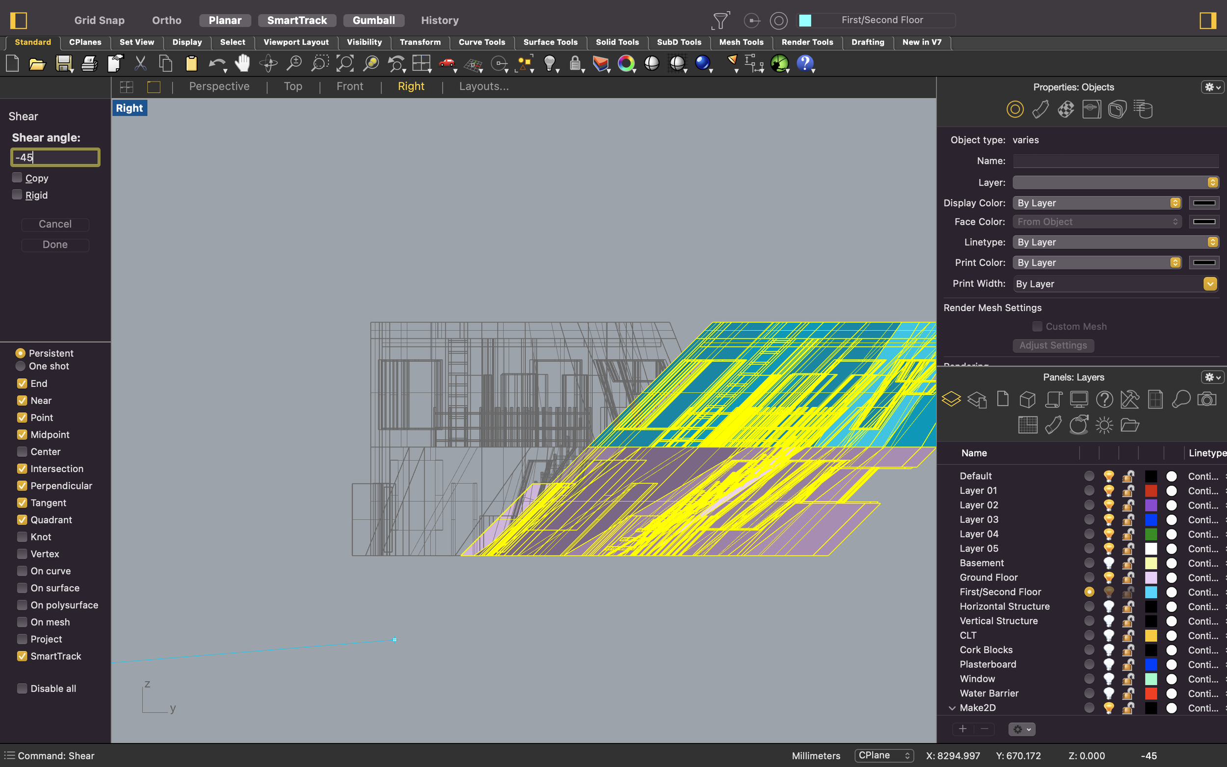
Type ‘Shear’ into your command box. You will be prompted to either select or type in an origin point. When asked, type in ‘w0,0’ as your origin point. This refers to the world origin point. Tap enter once done. You will then be prompted to type or select a reference point. For this prompt, type in ‘w0,0,1’ which is 1 in the direction of the Z axis. Tap enter. Then you will be asked to enter a shear angle. Type in -45 degrees and then tap enter again.
5. Make2D
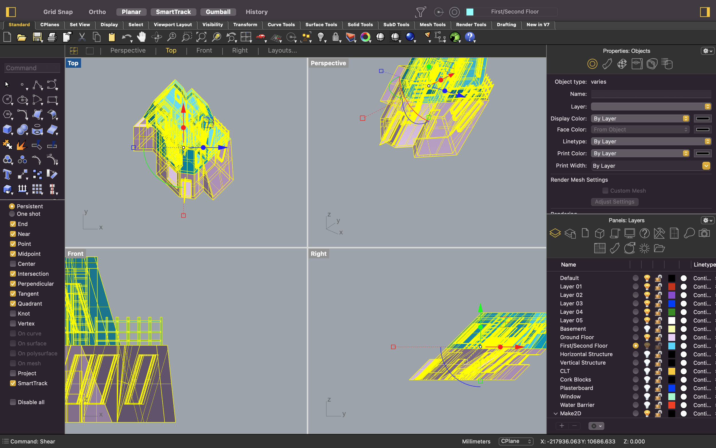
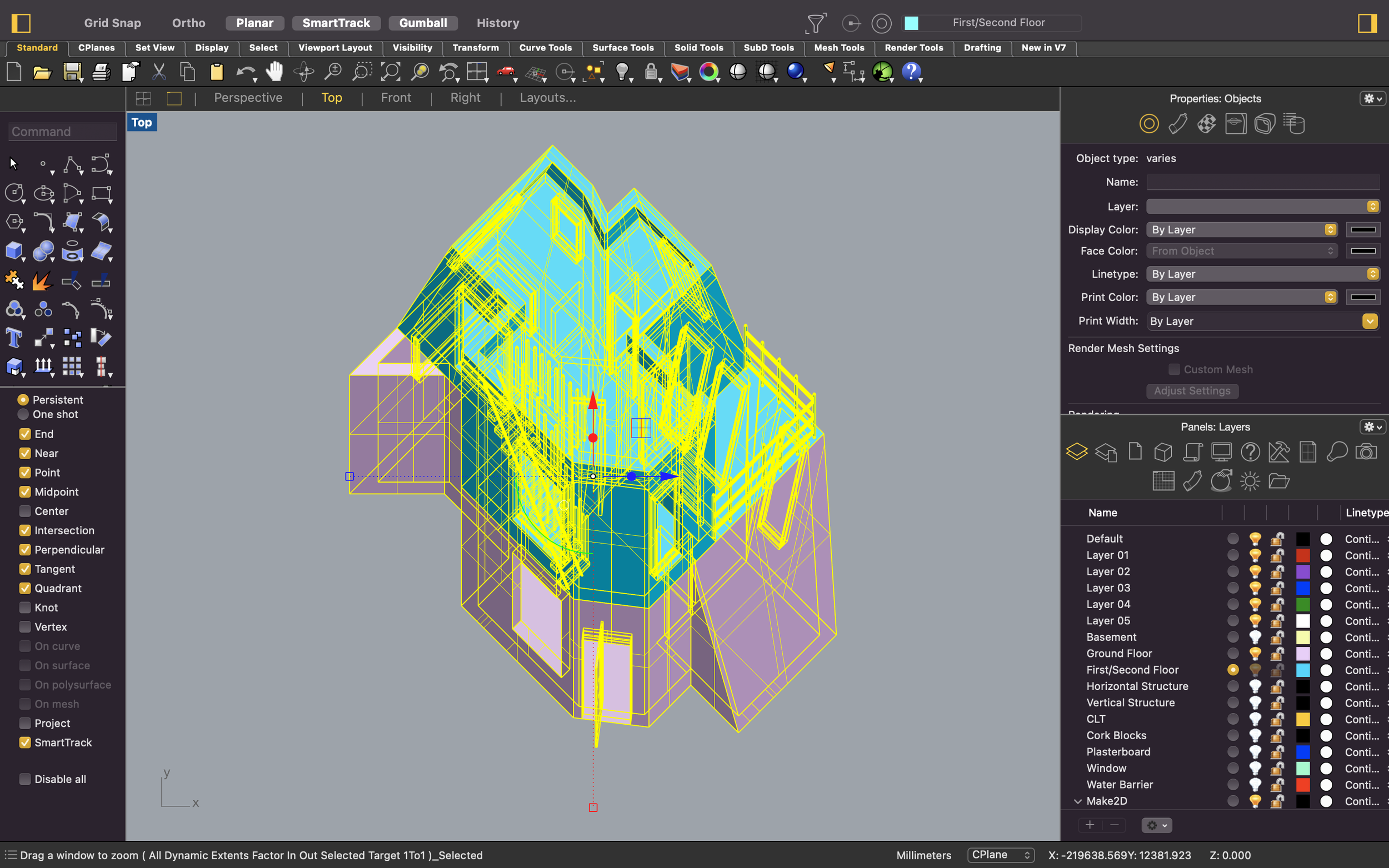
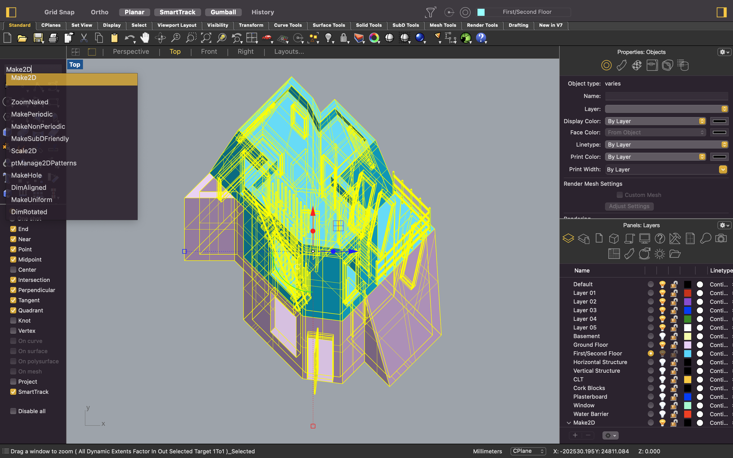
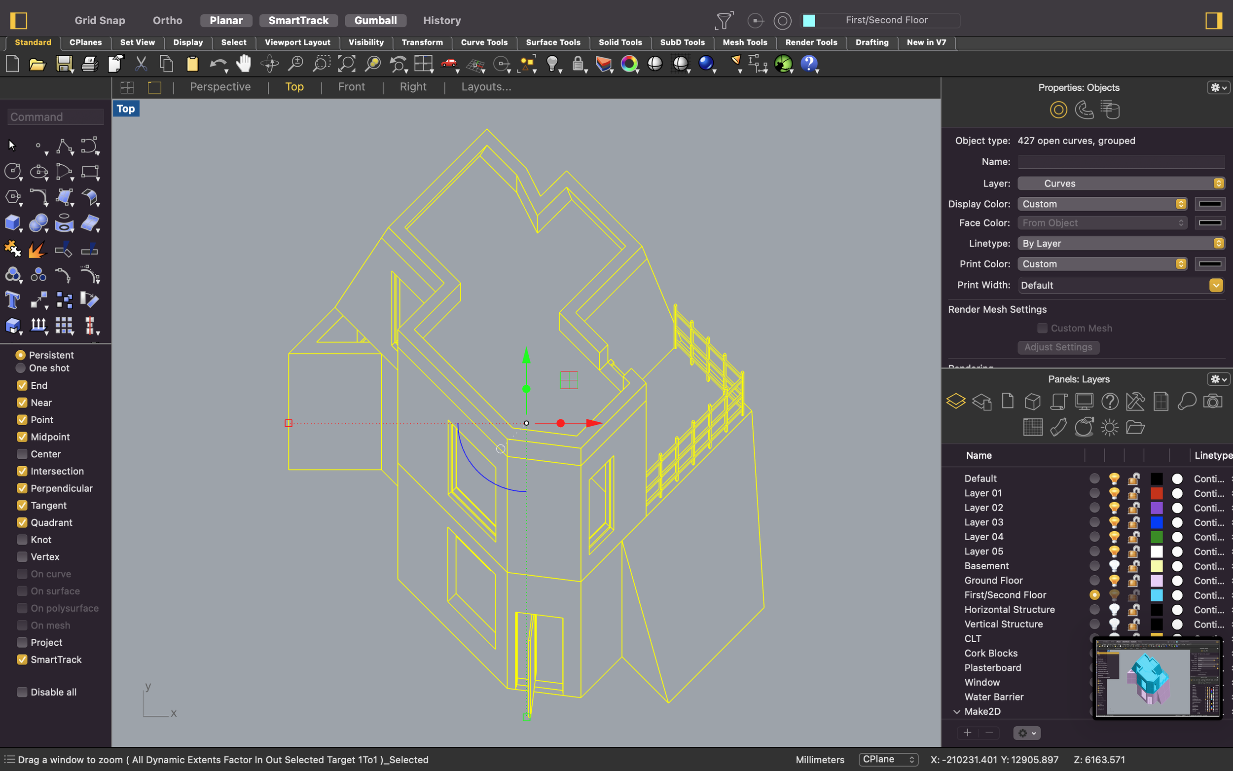
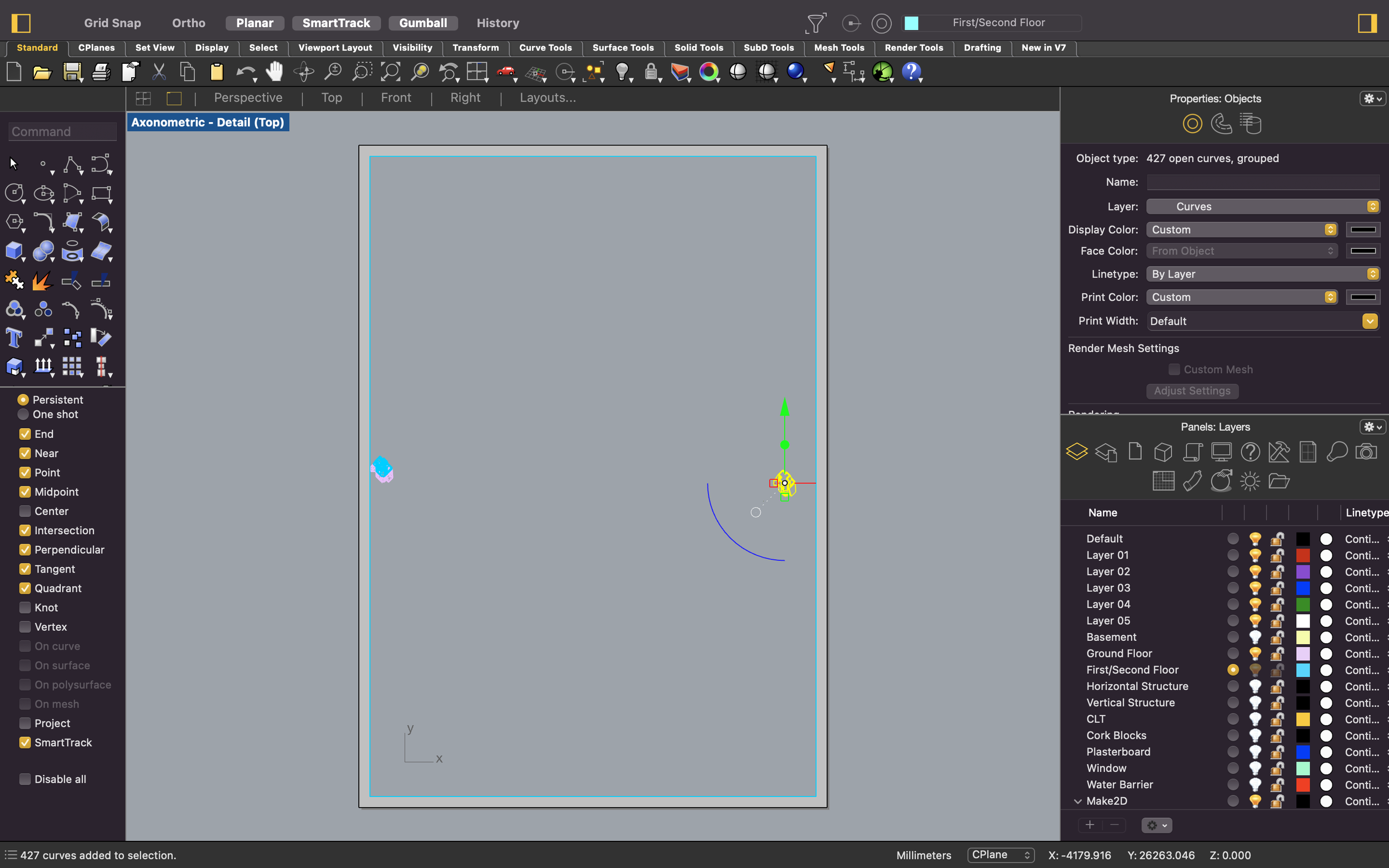
If you go back to your 4 viewports, you’ll see in your ‘Top’ view that the model is now in axonometric projection. You can now simply generate a 2D drawing of the 3D projection by using the ‘Make2D’ command in Rhino.
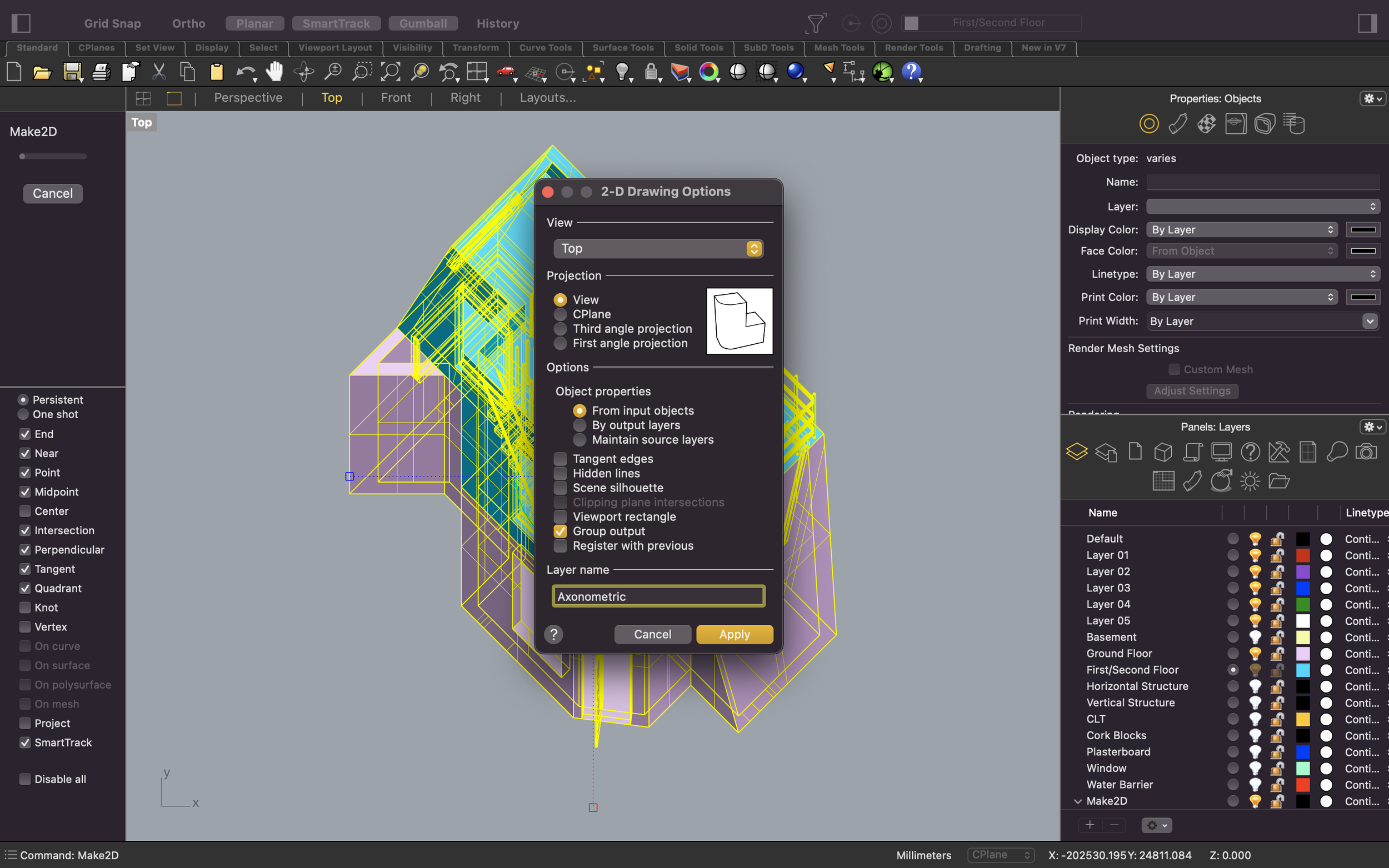
Whilst having everything selected, type in ‘Make2D’ and tap enter. A make2d window will automatically pop up. In this window you can select what view, object properties and name options you would like for the 2D drawing. Make sure to have the top view selected in the drop down menu. The other options are up for you to decide based on your preferences. You can see below in the screenshot what options I have selected. Once finalised, click apply which will then generate a 2D line drawing of the 3D model.
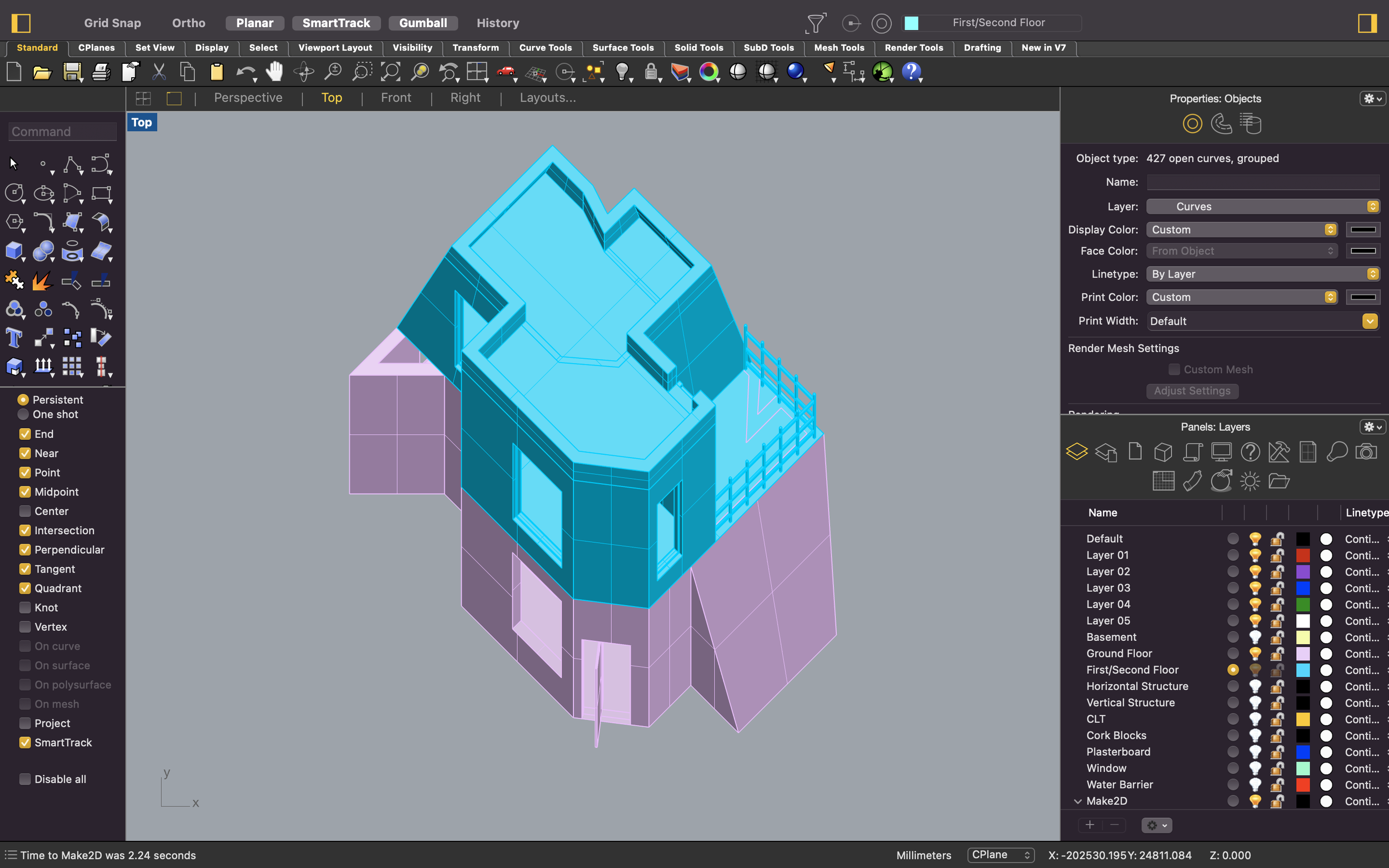
This task shouldn’t take too long but the time taken can vary on the complexity of the model. Rhino will automatically have the 2D drawing selected once generated so you can use the ‘ZS’ tool to shift your window to the drawing.
6. Layout & Print
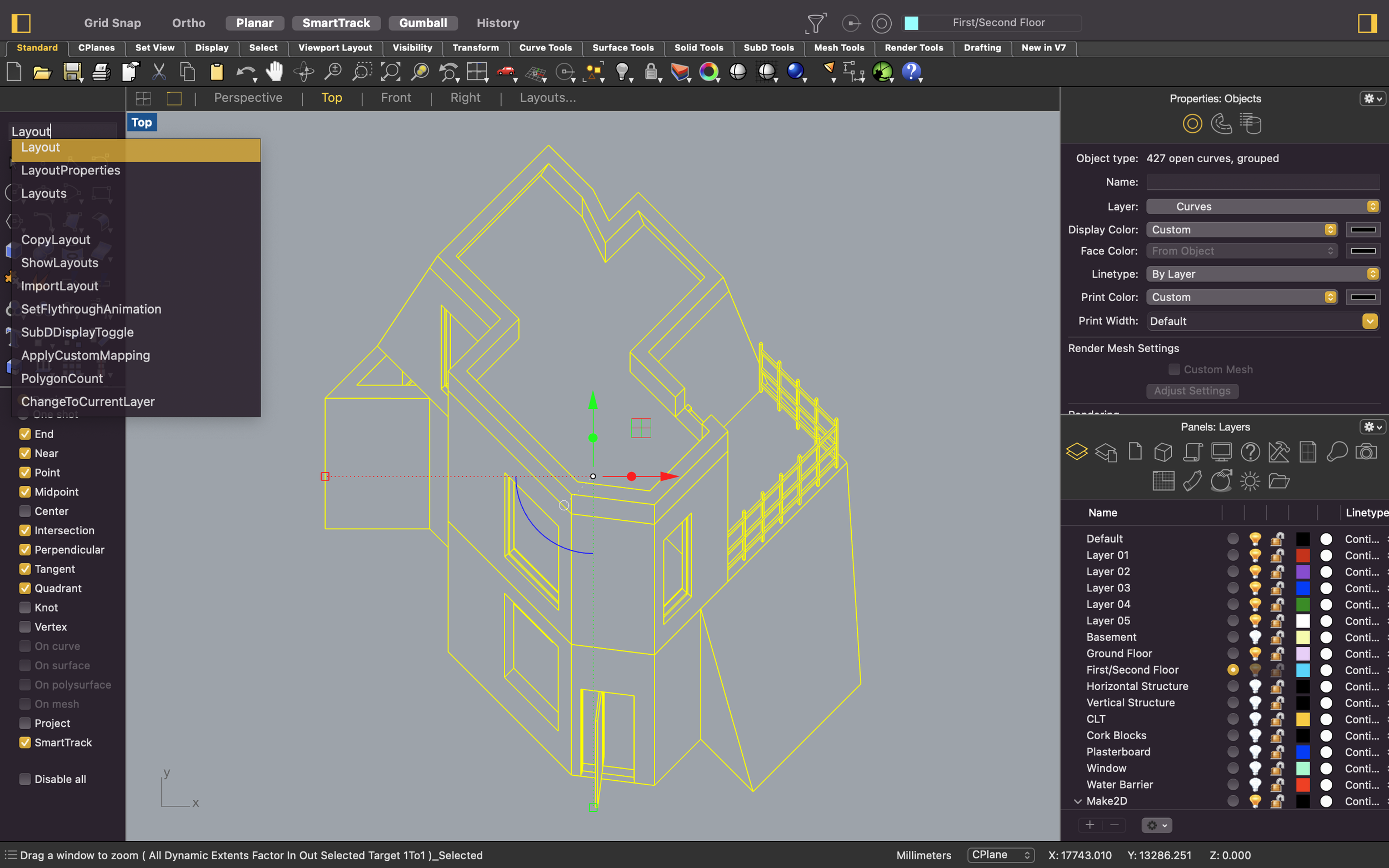
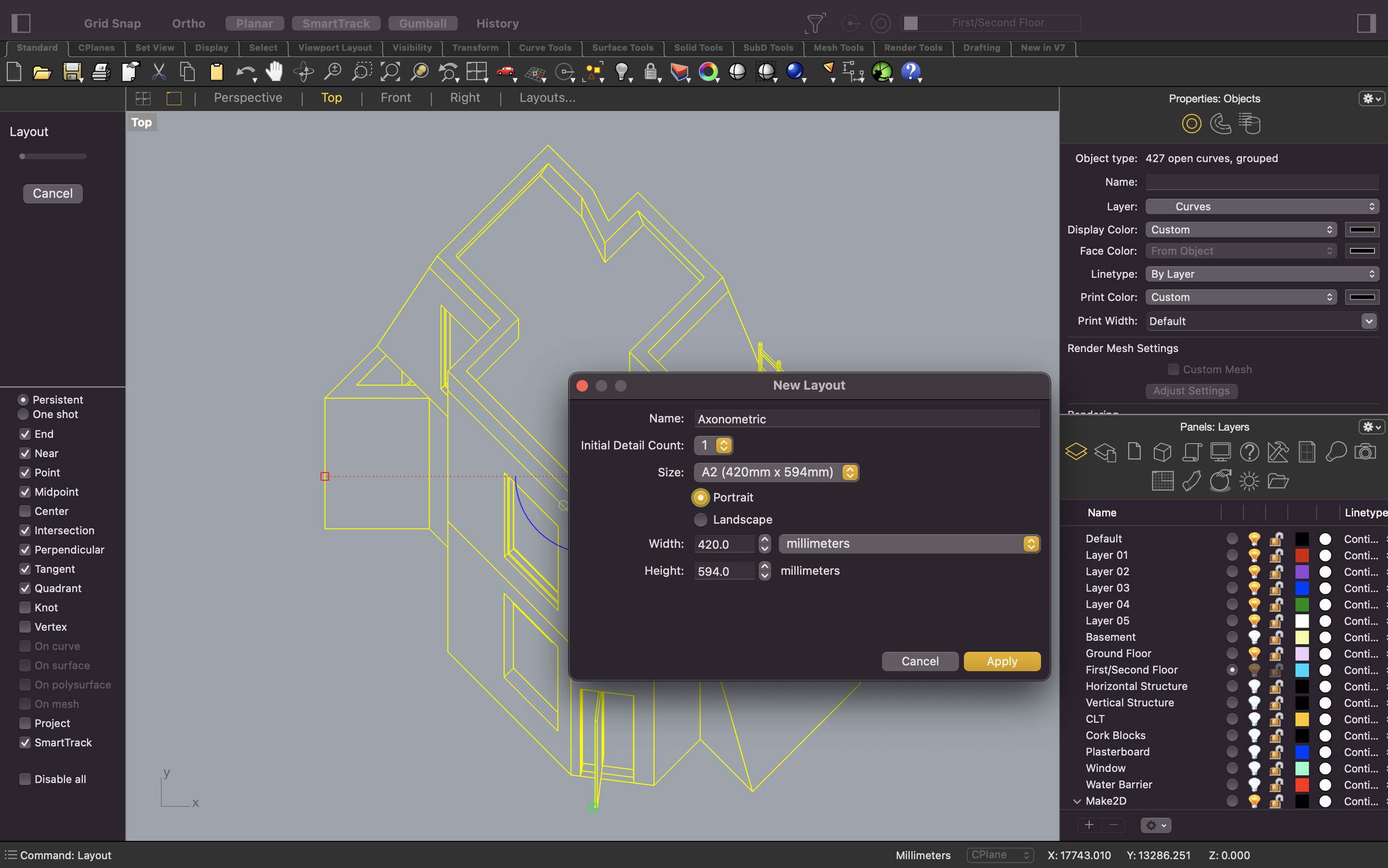
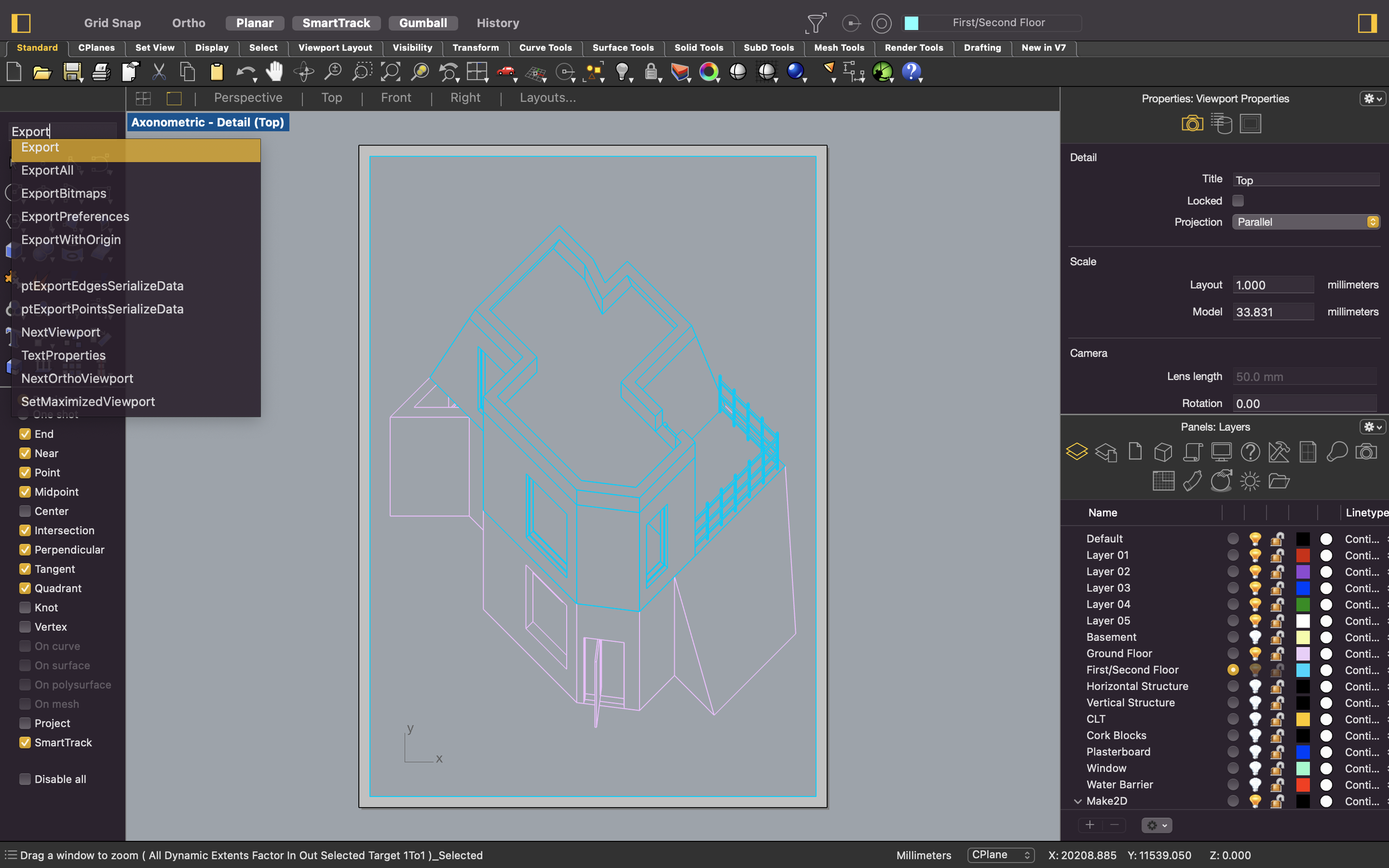
We will be using the ‘Layout’ function to format the drawing onto a desired page size along with a scale. When you use the ‘Layout’ command, a new window will appear prompting you to set up the page you will be placing your drawing onto. Choose your preferred page dimensions and click apply. You will see a grey bordered page appear. This is your page which you will be scaling your drawing onto.
In the screenshot below, before exporting, you will see that you have the option to input a scale for the axonometric in your Viewport Properties. You can type in your wanted scale where it says ‘model’ underneath the scale segment.
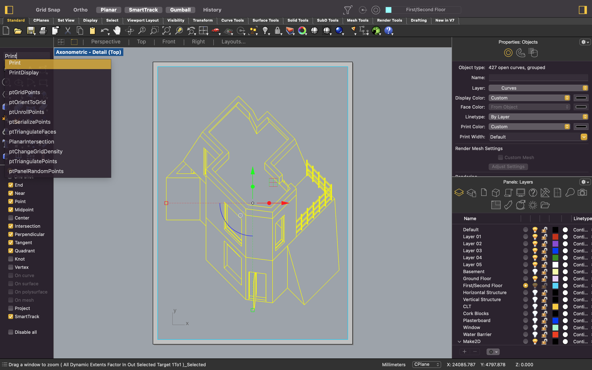
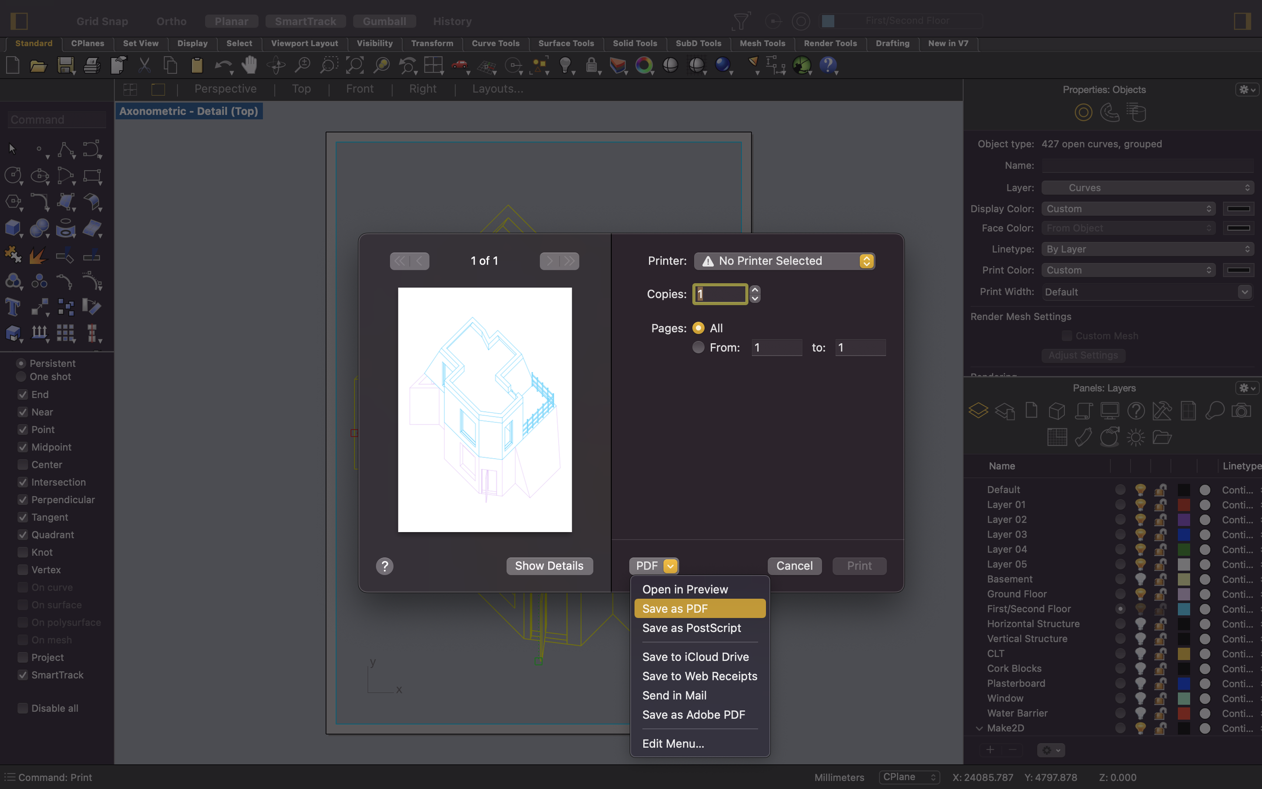
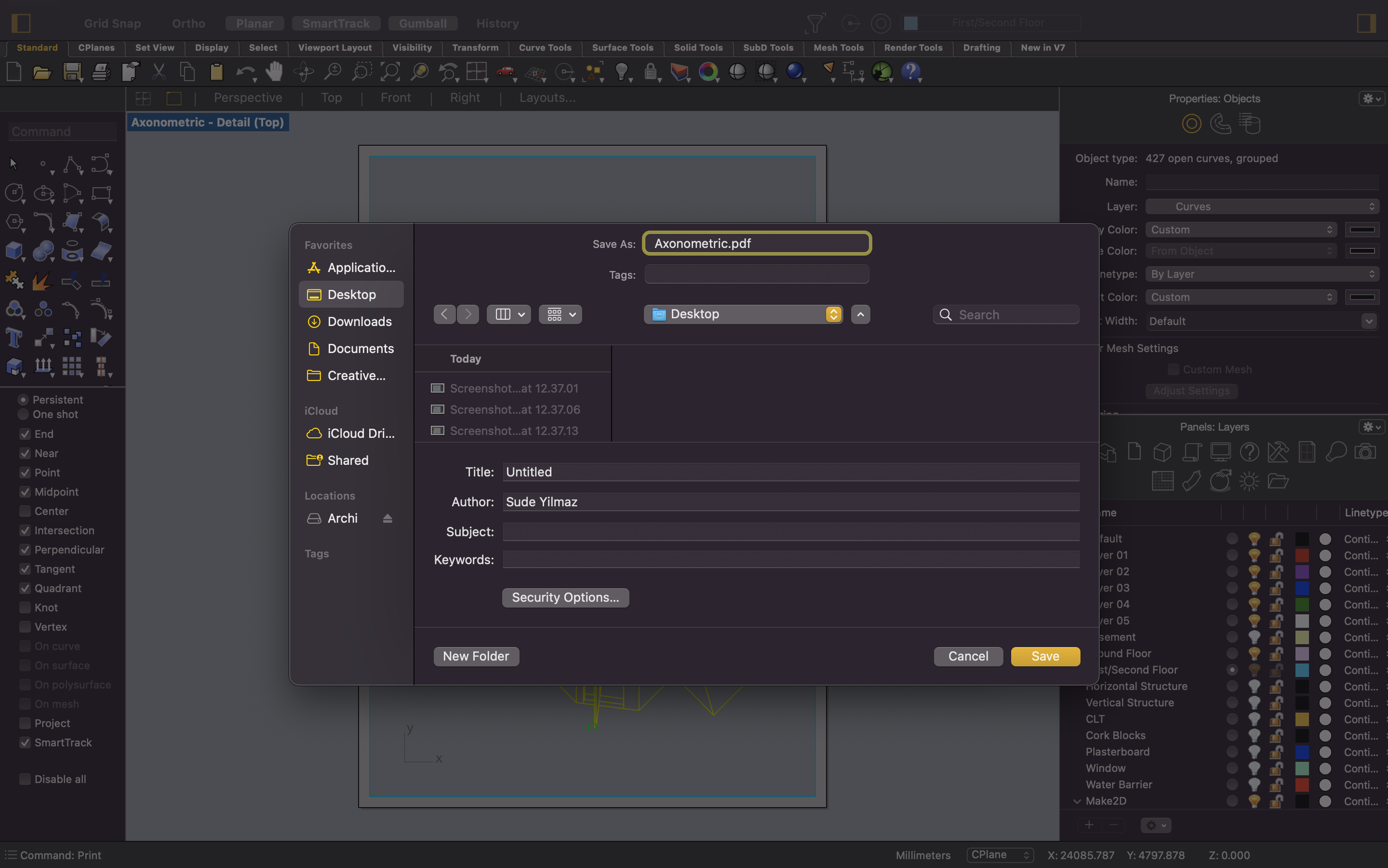
When you’re ready to generate your PDF, you can type in ‘Print’ and save the file.
The next steps would be to open the file in Adobe Illustrator in order to fix line weights and experiment with colour, textures and more. If you are wondering how you can do this, check out our ‘Post Production using Rhino & Illustrator’ which talks about the importing process and the basic Illustrator tools to edit your drawing.
That brings us to the end of this week’s tutorial blog post. Axonometric projections are another great way to visualise your ideas and design proposals and tend to be more successful in translating them from 2D to 3D.
Keep an eye out for future tutorials which will be covering the other projection drawings. In the meantime, check us out over on @archidabble on instagram for weekly content on Mondays!
See you next week :)