
Perspective Section/Plan Production
This week we’ve got a tutorial for you on how to produce perspective plans and sections using Rhino before taking them into other programmes for post-production. These kinds of drawings offer a new qualitative layer to traditional orthographic projections that can help narrate your project in a more detailed way, and represent the use of your spaces more dynamically and effectively. The post will use a section drawing as a running example, but the same logic and method can be applied to producing perspective plans as well.
Modelling
For this method of producing perspective plans and sections, you’ll need to model your proposal in enough detail to make meaningful cuts and position the main elements of your design in your drawing.
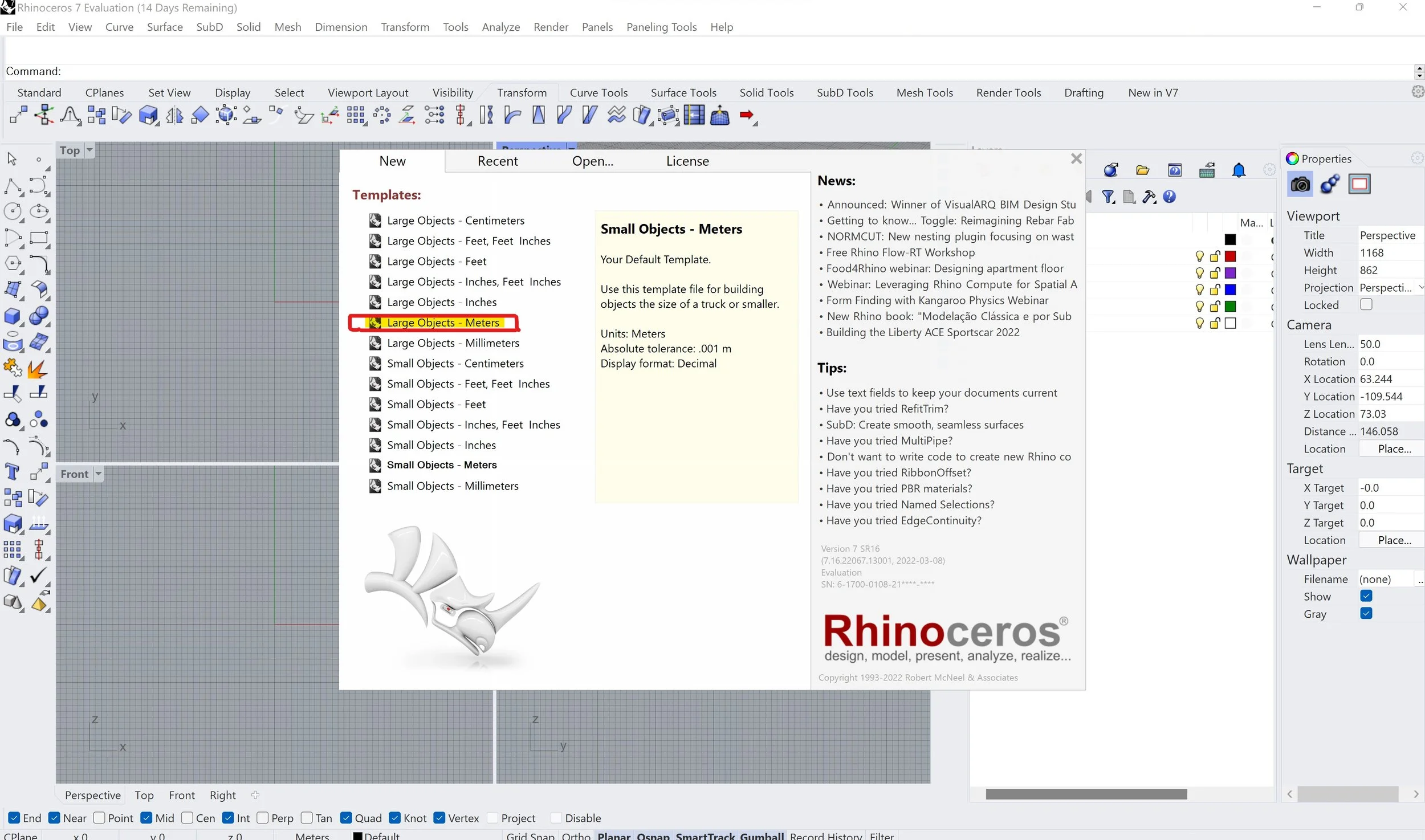
Step 1: Open up a new Rhino file on your computer. On the start-up menu, go to the ‘New’ tab and select the ‘Large Objects’ template. We will be scaling down the drawing after extracting the projection of the model, so you can model the elements at 1:1 scale.
The scale of your desired output of your drawing will inform the amount of detail and type of geometry you will be modelling with. For example, a wall at a larger scale that doesn’t demonstrate the construction layers will need solid poly-surface walls, as hollow shapes will mean you need to cap these after determining your section cut or fill these in during post-production. On the other hand, a wall with more details will need to convey each layer at an appropriate detail, keeping in mind that intricacies need to be compromised with the cut line weight of the thickest layer of your orthographic. If your wall is too detailed for the scale you’re drawing at, the details will be too thick to distinguish - you will either need to simplify the details or export your drawing at a bigger scale. An alternative way to convey the detailing is to model the cut walls as plain solids, then project a normal sectioned 2D drawing of the details onto this solid wall in Photoshop after exporting. This is a good option if your details are already drawn in 2D, or if you aren’t confident with modelling construction details intricately in 3D.
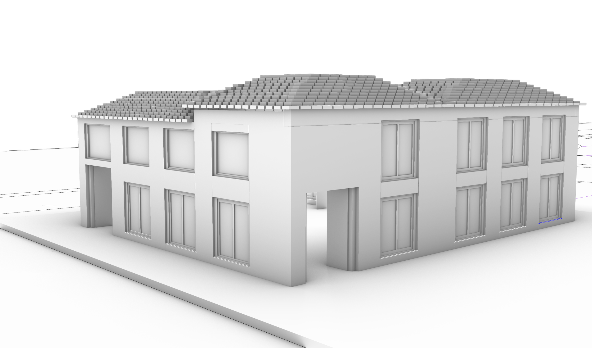
Step 2: Model your building geometry using poly-surface solids or blocks. For this tutorial, I’ve used a very simple model but you can make it as complex or as simple as your drawing needs to be.
Cutting and Positioning
You’ll need to decide where to cut your proposal, in the same way, that you would consider a normal sectional cut to best represent the ideas you’re showing. Ideally, you will want to cut your building where you can show a variety of spaces that flow as you move through your section, highlighting the meaningful parts of a user’s journey through your proposal as seamlessly as possible.
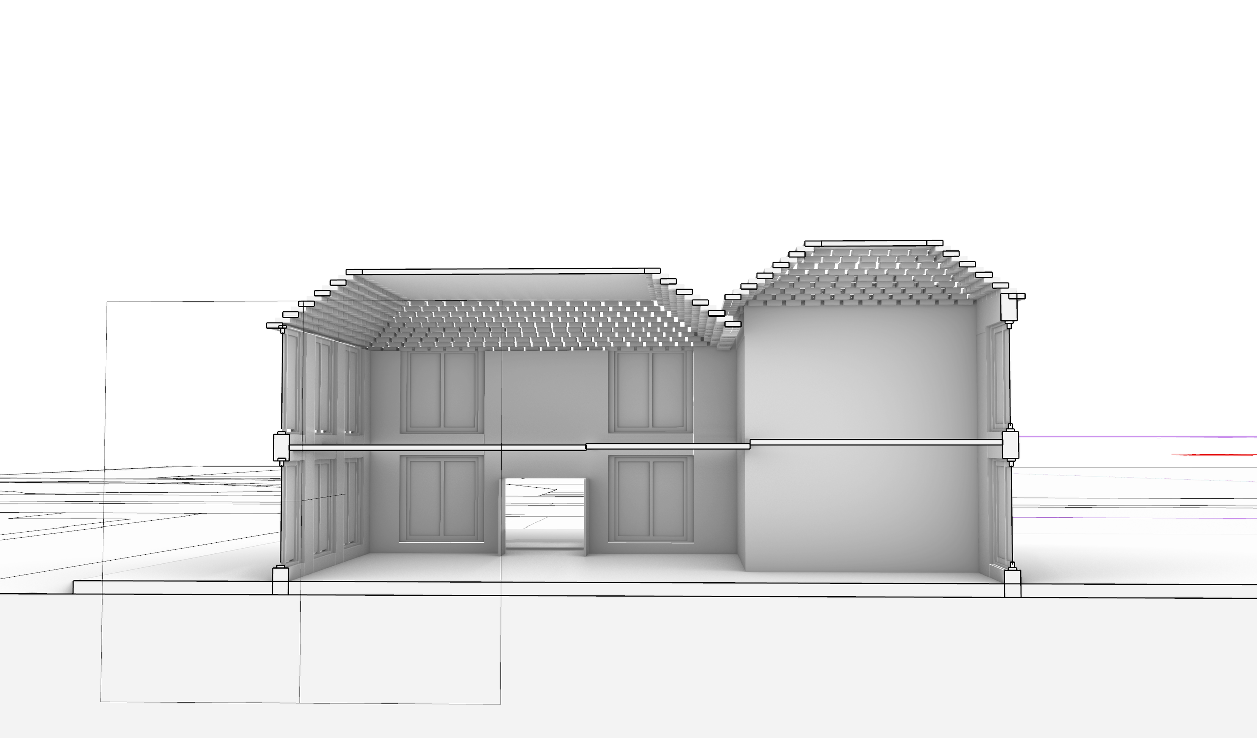
Step 3: Use the ‘Clipping Plane’ command to slice your model where you want your cut line, positioning and rotating it with the gumball tool.
Step 4: Next, you will want to position the camera so that it is parallel to the floor that divides the objects above and below eye level. Go to perspective mode in the Rhino viewport menu and drag/rotate the window until it is in the correct position for your drawing.
Export
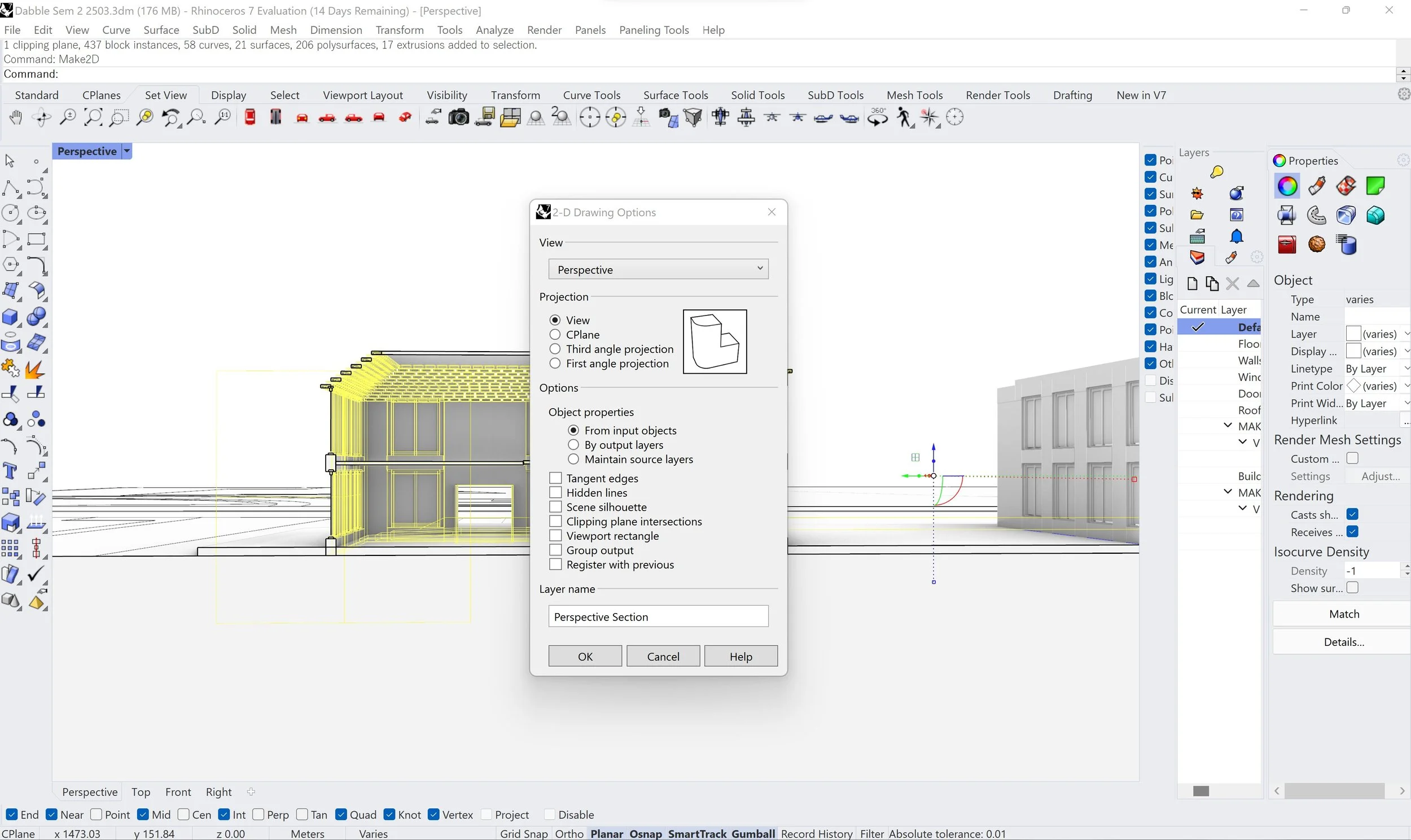
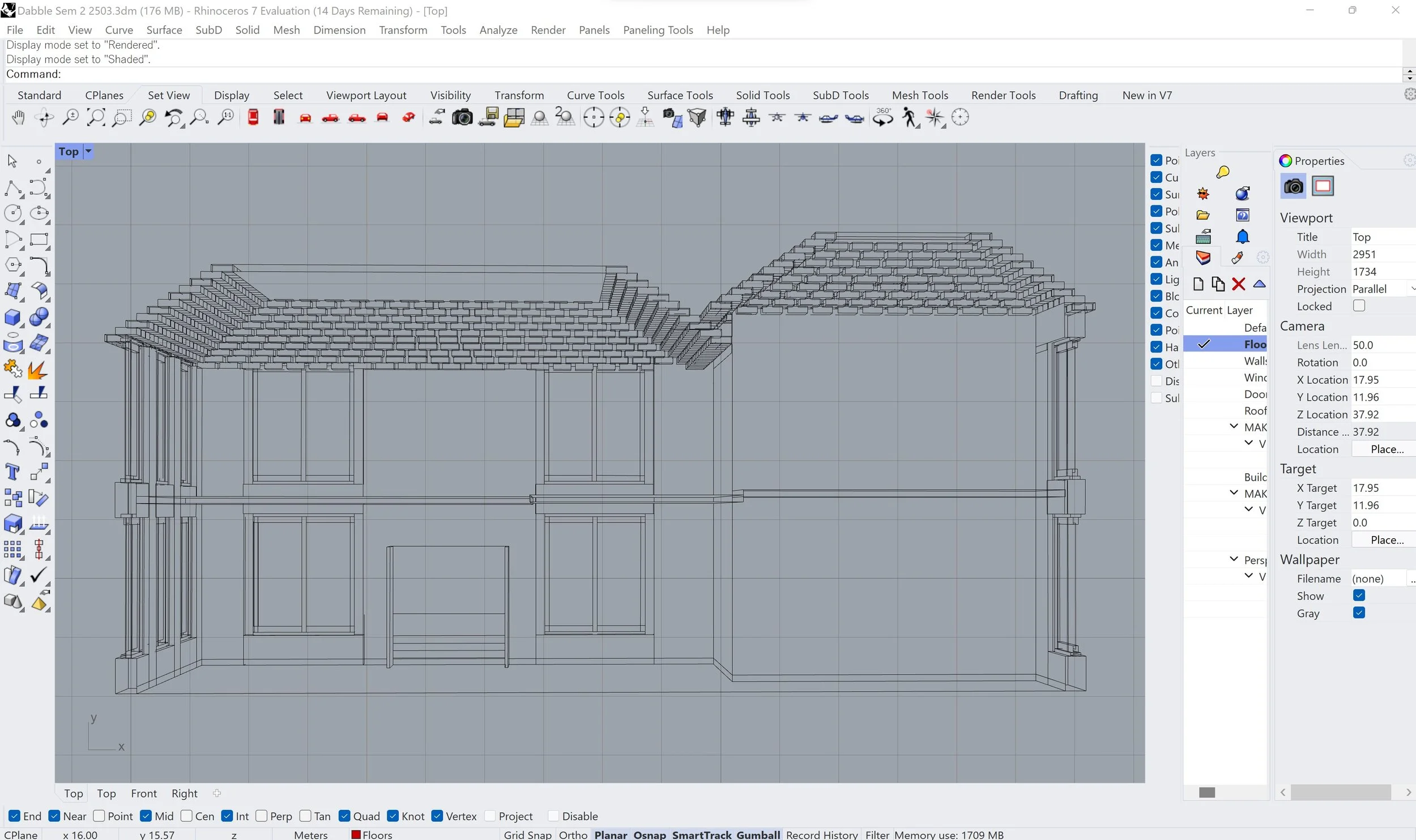
Step 5: Use the ‘Make2D’ command to capture the line drawings of your model into a different layer. Press ‘ZS’ to zoom in to the drawing, and trim down the excess lines to clean up the drawing before post-production. Make sure you are in ‘Top’ view for this part of the process.
Step 6: Select the Make2D drawing and scale it to the size you need for your final perspective section. Use the ‘Scale’ For example, if you want a 1:50 drawing, type in ‘1/50’ for the scale factor when executing the scale command.
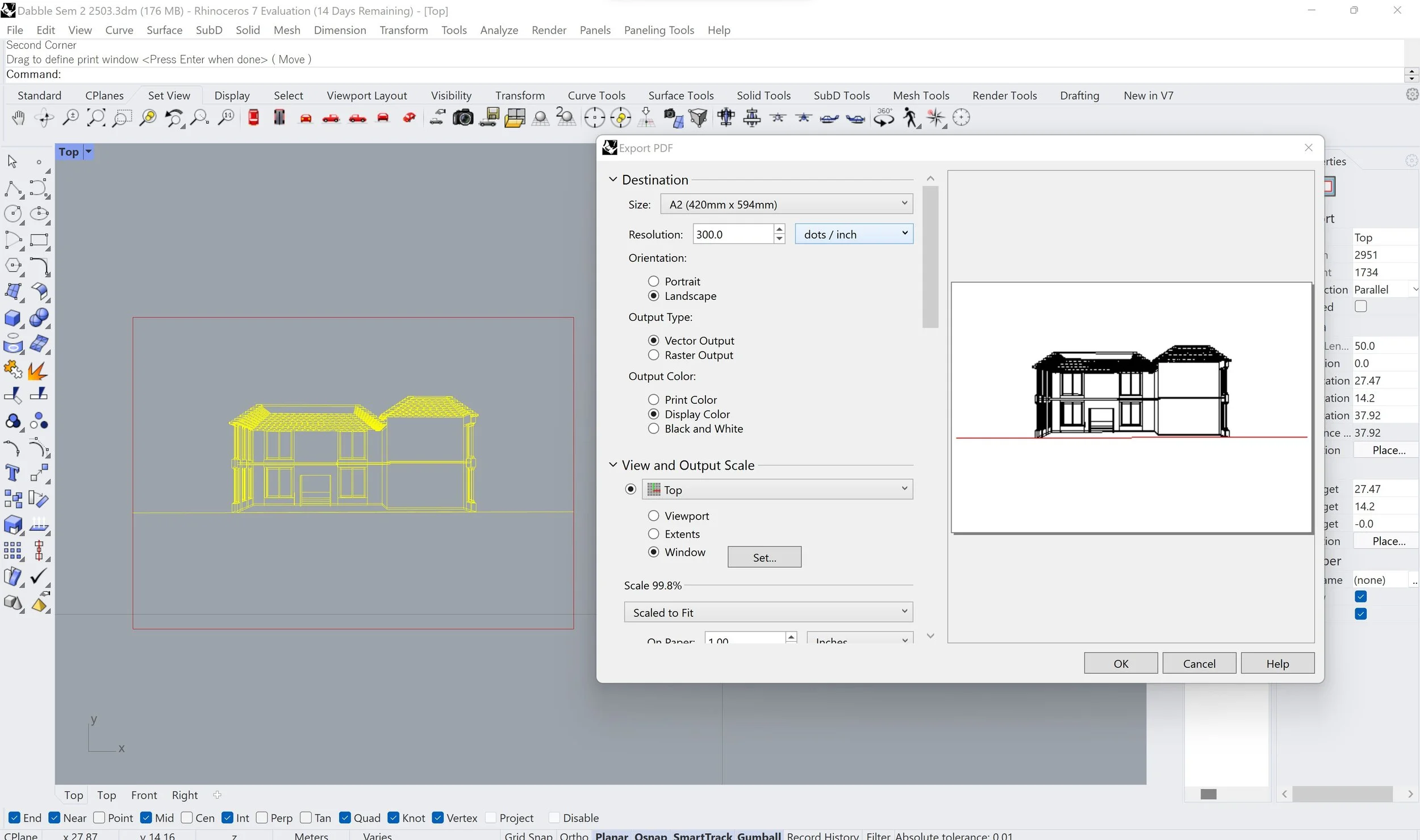
Step 7: Now, draw a rectangle the exact paper size of your digital drawing and position it on the Make2D drawing to set the boundaries of the contents of the section. Select everything but the boundary line and use the ‘Export’ command. When given the option, set the ‘Window’ of the extents of your drawing to the rectangle you drew that represents the page size your final drawing will be. Export and save as a PDF on your computer.
Post-Production
Now, you can take your PDF of your perspective section into other programmes such as Illustrator and Photoshop to render textures, change line-weights and add details like furnishing, people and shadows. For certain features that will be in perspective like furniture and/or context, you may find it easier to model these in Rhino and render them as 3D objects.
To find out more on how to process your orthographics in Illustrator and Photoshop from Rhino, check out our posts for these extra skills we have written about for you guys under our ‘Tutorials’ section of the blog.
We hope you found this post useful in learning how to produce the base of a perspective section or plan drawing from a 3D model in Rhino. Keep an eye out for our next tutorial where we will be covering the basics of rendering in Lumion.
Don’t forget to check out our CAD Store and follow us on Instagram to stay up to date with our latest content.
See you next week for another blog post!