
Vectorworks Basics
Vectorworks is one of the many software programmes that allow you to form digital representations of your work in the design industry. It is a program that can be used for 2d drafting, 3d modelling and rendering of your drawings. Similar to most other CAD and BIM programmes, it’s engineered to work with layers and different palettes to provide an efficient working desktop. It is also one of the few programmes that has a free student license! This post is going to focus on getting you familiarised with the 2D basics of Vectorworks in a tutorial format where we’ll cover a range of things from how to set up your document and how to use certain tools to how you can export your work.
Setting up a document
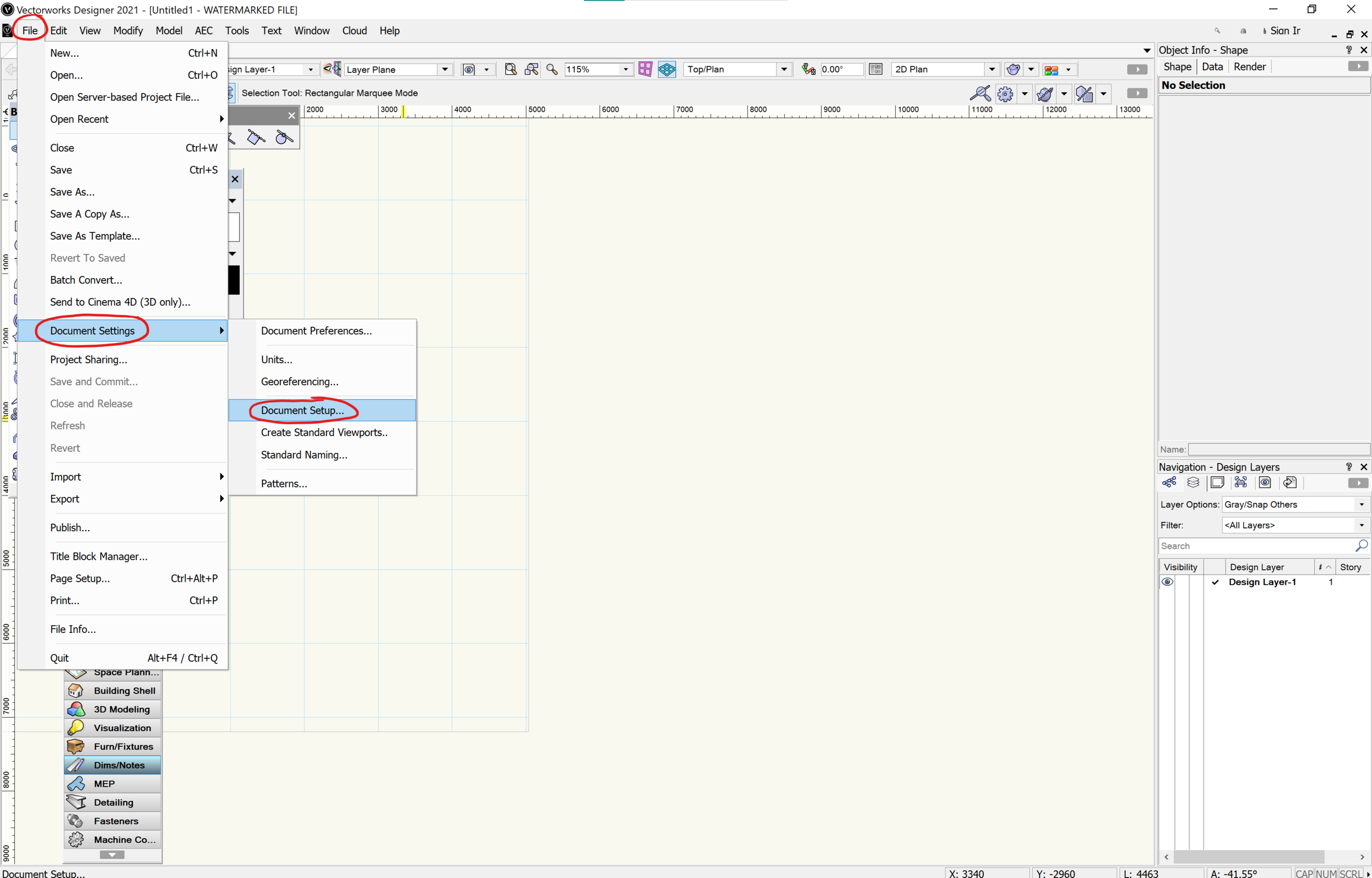
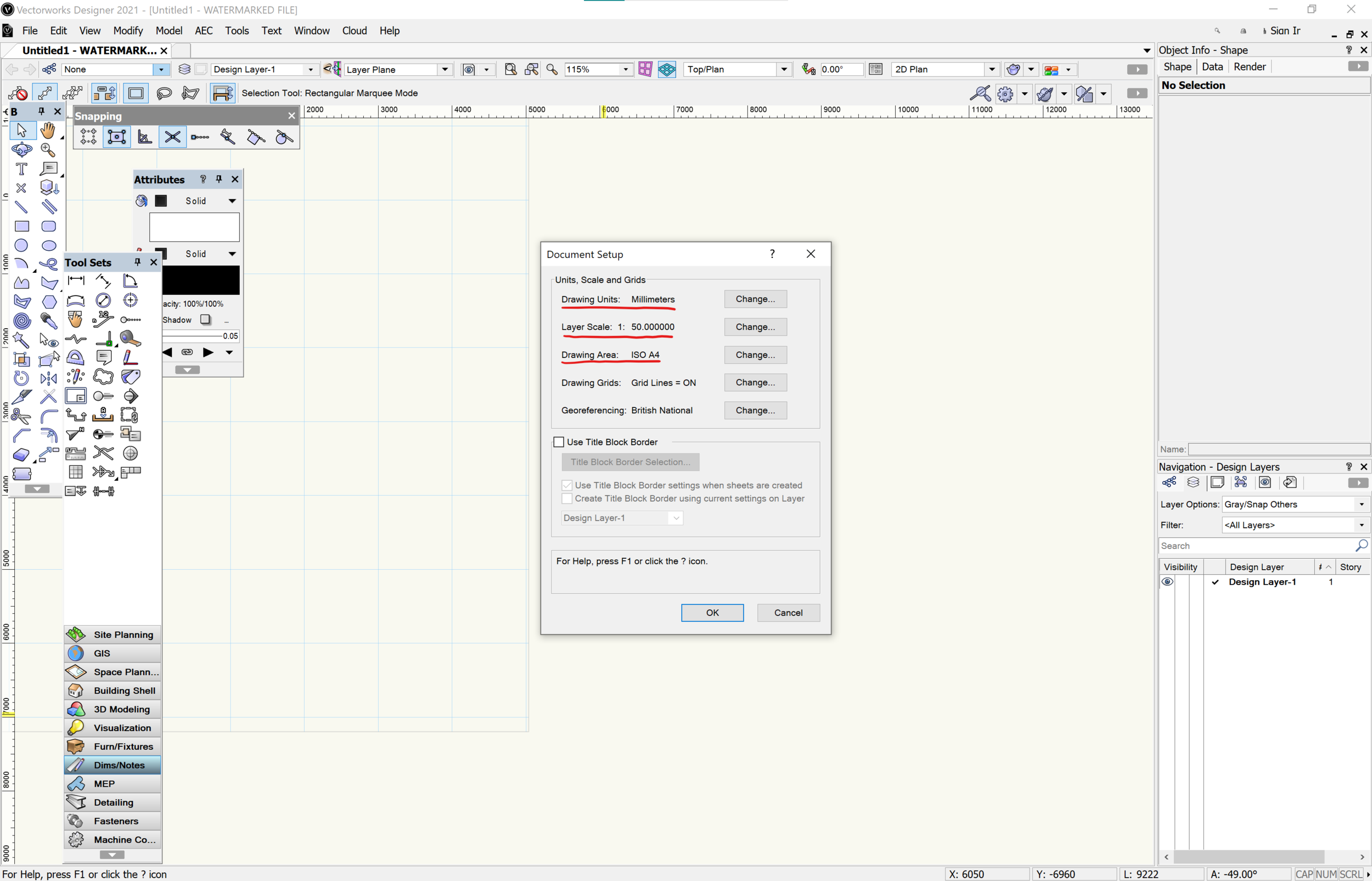
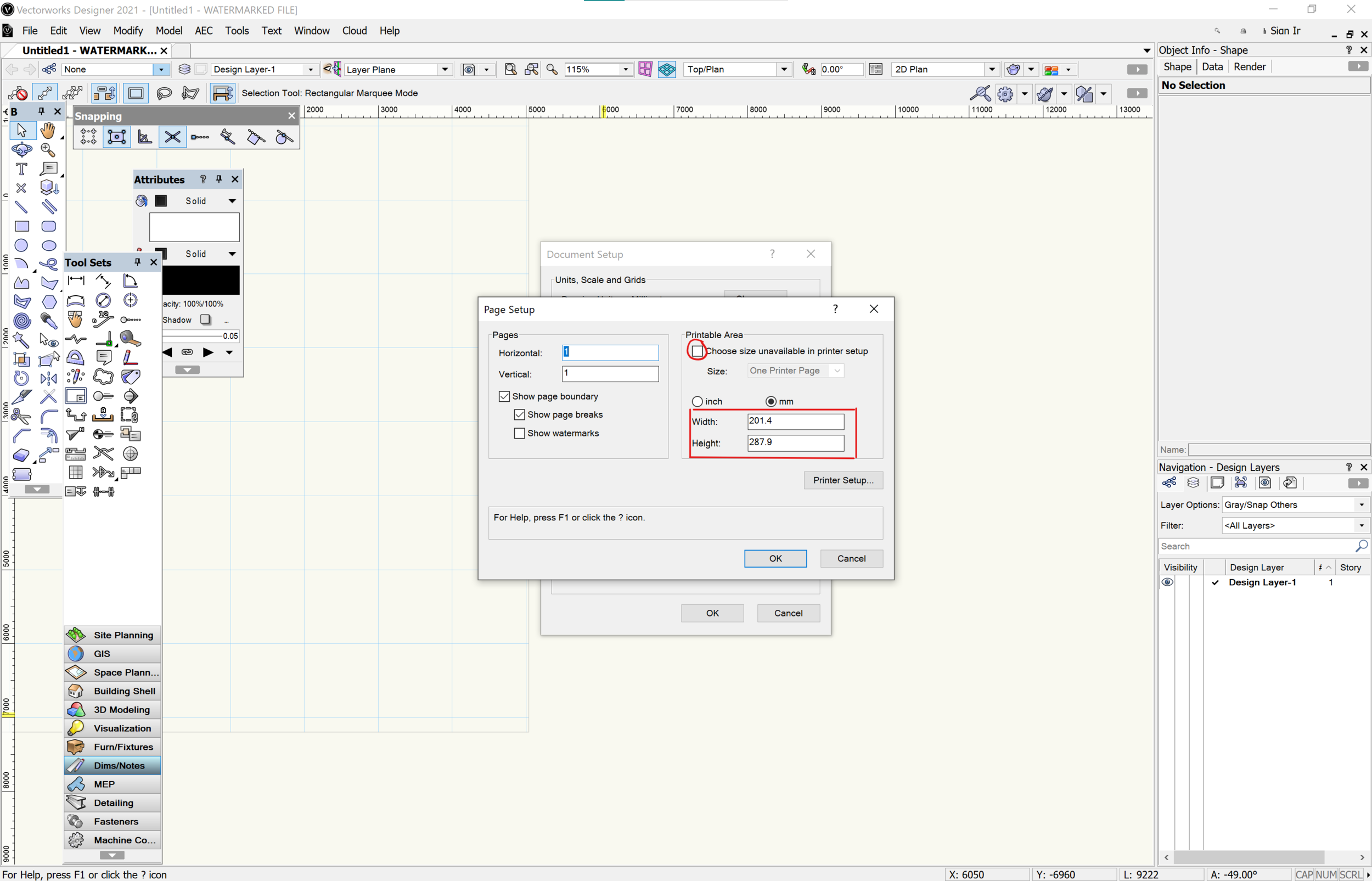
When you initially open Vectorworks a new page will open and the first thing you will want to do is set up the document with your preferred settings. To do this you go to File > Document Settings > Document Setup. Here you can change the properties of the document such as the units, the document size and the scale of the layer. i.e. Selecting the option for ‘Drawing Area’ allows you to change the page size either manually or by selecting a pre-existing printer size.
You can also activate a scale for the selected layer you are working on by right clicking on the page and selecting ‘Active Layer Scale’. This will open up a window of options where you can adjust the scale, again either manually or by a pre-set metric/imperial scale.
Palettes
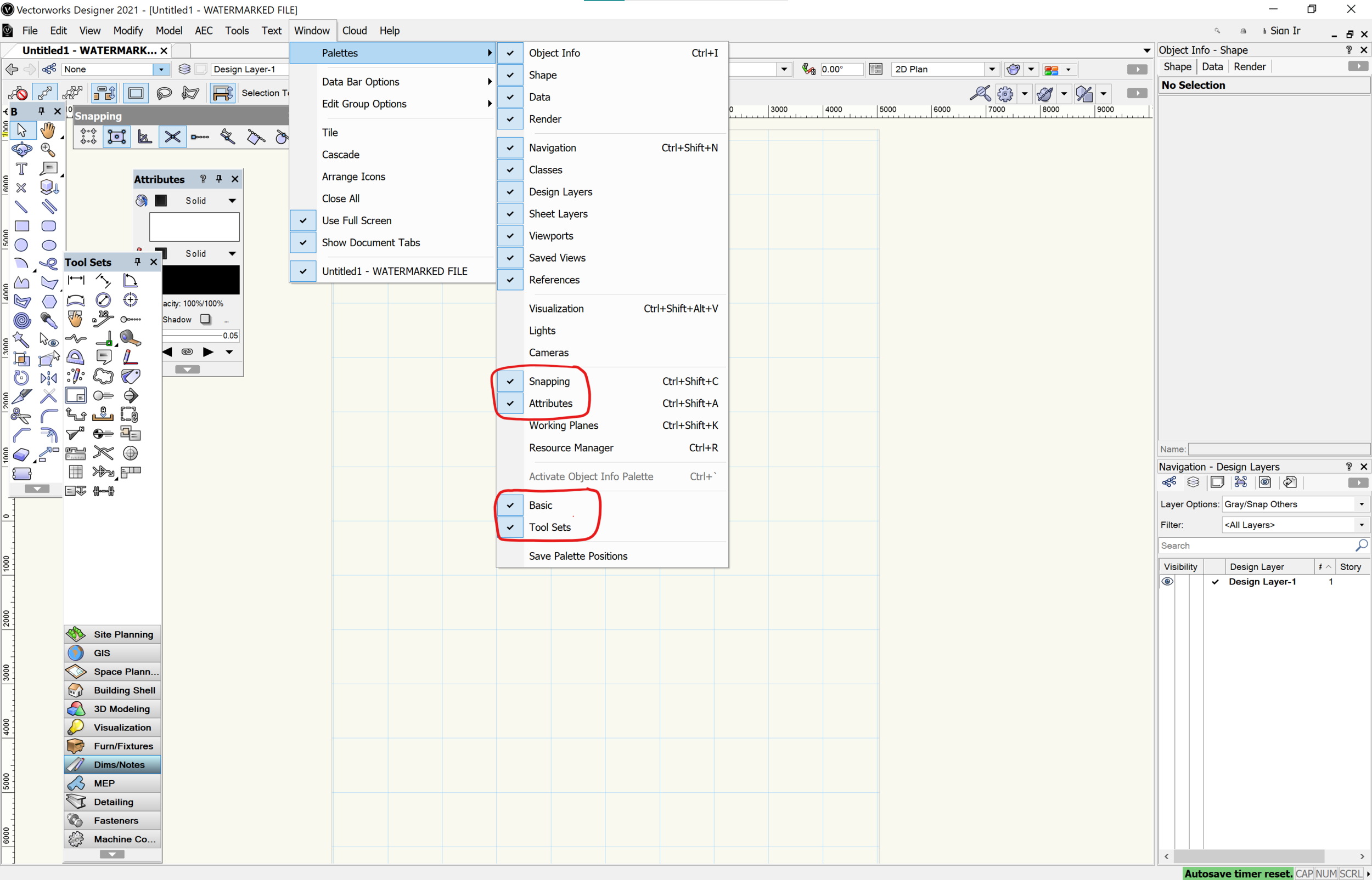
Palettes are like smaller windows containing tools that let you draw and edit objects. When you use Vectorworks for the first time, most palettes are hidden, giving you the chance to customise your work space with the tools and palettes you wish to work with. The first thing we want to do is make these palettes active. To view the options of palettes, you need to select Window> Palette. The palettes I will show you today are called: ‘Snapping’, ‘Attributes’, ‘Basic’ and ‘Tool set’.
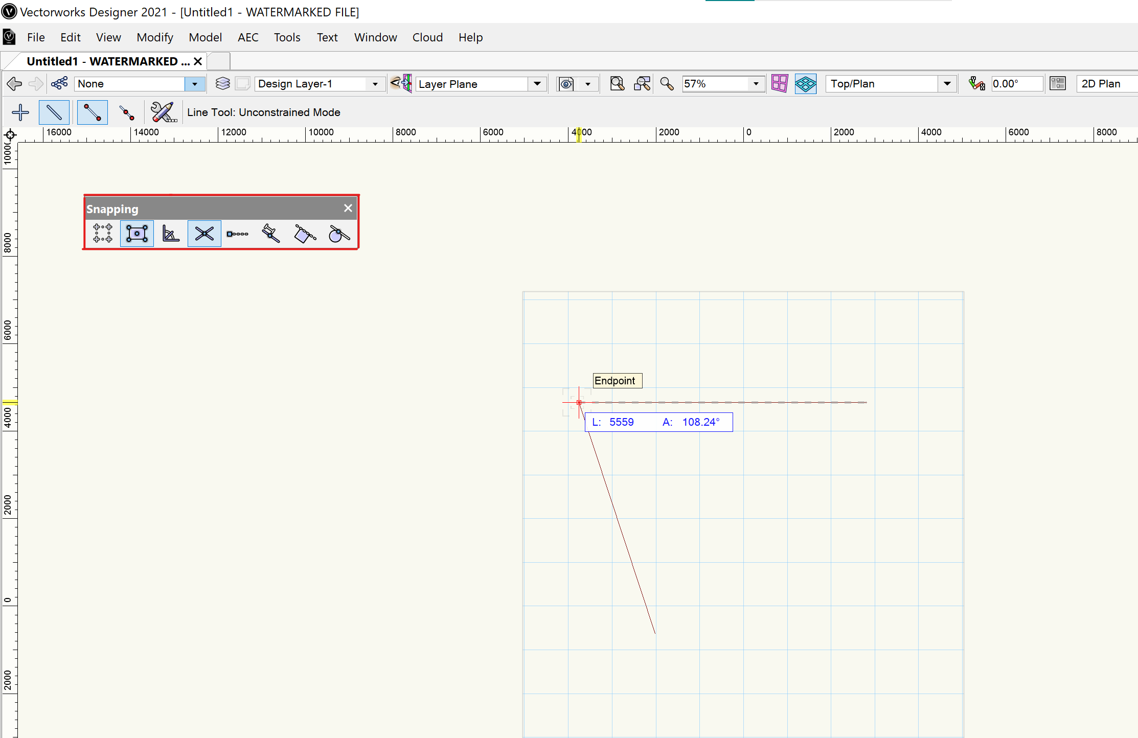
The Snapping palette handles the snapping controls, not only letting you turn it on and off but also allowing you to select the type of snapping you want. This function has both 2d and 3d palettes, in the image below I have shown the 2d palette. You can snap to the grid, which allows your cursor to fall onto the grid when drawing so lines meet. The other snaps available are: General snapping, snap to tangent, object snap and angle snap. The general snapping is most frequently used by me, as I have it the majority of the time to avoid time consuming issues like lines not meeting.
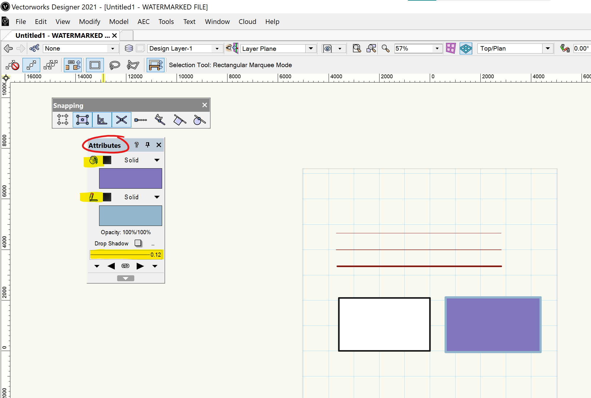
The attributes palette lets you decide the colour, weight and fill of an object, line, shape etc… This is the palette I use to group my line alignments with my orthographic’s. As well as these functions it also includes mark endings, drop shadows and an option to decide the opacity.
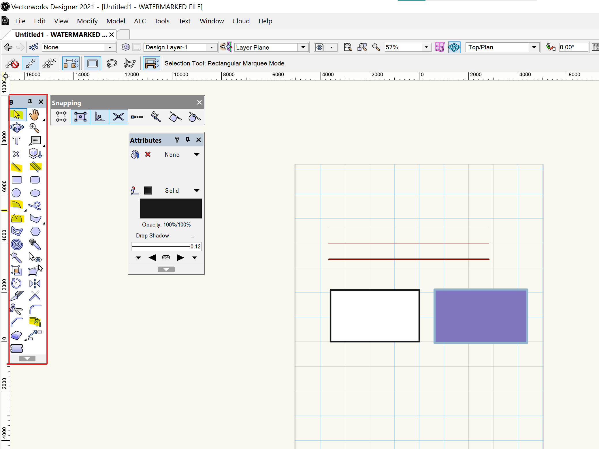
The basic palette is one that includes everything necessary to draw. Some examples are the offset tool (great for wall thicknesses), line tool, polyline tool etc.... This palette will always be open on my screen as I use it for everything! (I have highlighted my most used tools in yellow)
Tool set is the more complicated palette. It is made up of 12 sub-sections which hold tools specific for that category. The Section I used most often in my simpler drawings was Dim/Notes which contains the scale bar tool, the north arrow and the section-elevation line. Other than this, I used the staircase tool which allows you to enter the number of rises, the type of staircase and the value of each rise to calculate your stairs for you! This can be found in the Building Shell section. With this palette, the more you develop your orthographic skills, the more you can take advantage of tools, eventually even using sections like the 3d Modelling and Building Shell to model your designs.

Layers
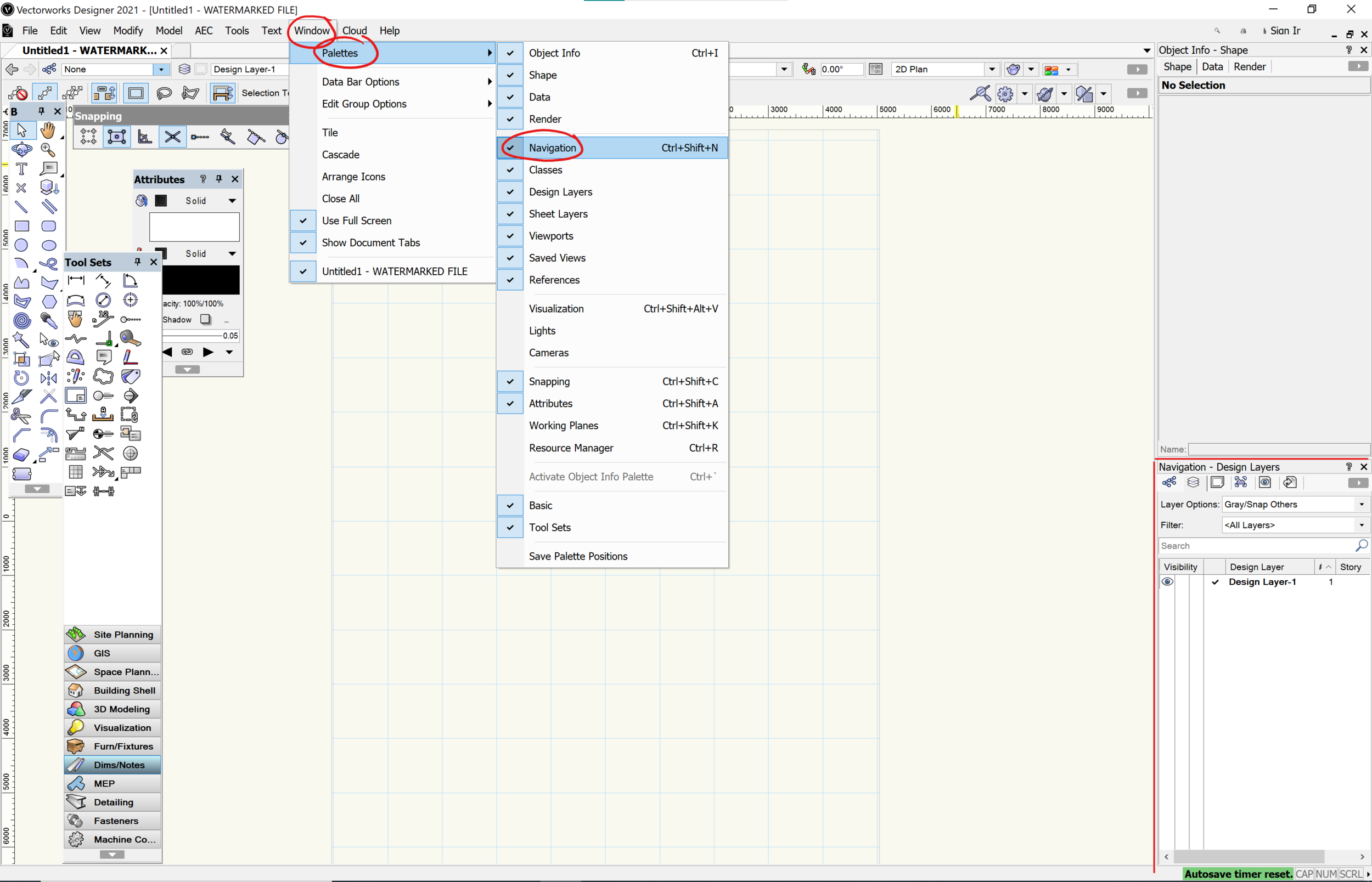
As I previously mentioned, Vectorworks works with layers. You can choose how to use your layers for objects. For example, you can assemble your layers to have one floor plan per layer, an element like windows (across all plans) on the same layer or you can have different layers for each type of drawing (i.e. plans, sections and elevations). In order to open the layer bar you need to go to Window > Palette > Navigation. This will open a section allowing you to view, create and delete layers.
In the standard document you will see a single layer called ‘Design Layer-1’. To rename this simply double click by the name and type in the new title. To add a layer you can right click and select ‘New..’ This will create the new layer where you can either rename the layer and create it, or you can import a design layer from another document. To select the layer you just created, all you have to do is double click to the left of the layer name. Once selected, it will be indicated with a tick. To delete a layer all you have to do is right click whilst hovering over the layer and click delete. Once the layer is deleted you cannot retrieve it.
If you look at the Layer bar you will also see a section called ‘Layer options’. This lets you choose how visible the layers not in use can be.
‘Active Only’ - Only the selected layer is shown
‘Gray Others’ - All remaining layers are greyed out. They are visible however not editable, helping you distinguish between the different layers
‘Gray/Snap Others’ - All remaining layers are greyed out. Whilst you still cannot edit them your object can snap to points on the grey layer
‘Show Other’ - All layers are shown on the document
‘Show/Snap Others’ - All layers are shown and can be snapped to on the document
‘Show/Snap/Modify Others’ - You can see, snap and edit all of the layers, even if it’s not selected as an individual layer.

Lastly, I'm going to explain how to change the layer of an object. You need to select the object you want to move. Then in the ‘Object Info- Shape’ palette there is a section called ‘Layer’. When you select it you will see a drop down menu of the layers in your document. Here you select the layer you want the object to move to and you’re done! That object is now under your new layer.

Exporting
To export your work go to File > Export > Export PDF Once you have exported with the desirable settings in the window, you might notice that the line thickness has messed up and it’s not looking like what you had drawn on Vectorworks. To solve this issue you need to save the pdf, open it again and export it one more time (double exporting). After double exporting you’ll see that the line weights are back to normal and from here you can take the pdf into photoshop to start rendering with textures, colours etc..

We hope this post explaining the basic setup and tools you need to get started in [2d] Vectorworks has been helpful. To make this tutorial as memorable and effective as possible, open up the software alongside this post to follow along using the tools. Don't forget, You can share your drawings with us by tagging us on Instagram! If you enjoyed this post go follow us on Instagram @archidabble to make the most of our weekly content on Mondays and Fridays!