
Orthographic Drawings in Construction Packages
Throughout our years in architecture school, our tutors always advised us to keep words to a minimum and let our drawings speak for themselves. After all, portfolios are not marked with you present in the room explaining your project from start to finish.
However, these past months (almost a year) in practice have proven that this isn’t always the case. In the context of construction package drawings, for those of you based in the U.K., this term refers to the drawings produced for RIBA Stage 5, drawings are everything but aesthetically pleasing. There’s always a slight effort to make everything look cohesive but the number 1 priority with these drawings is to communicate your intentions as clearly as possible and get the most out of one drawing. With construction, the drawing is never enough. It needs to be annotated thoroughly referring back to other types of documentation such as schedules, detail drawings, and sub-contractor drawings (Structural Engineer, Landscape Designer, etc). Hence, the contractor knows how something is being built.
“The Drawing Should Speak for Itself”... Really?
Potentially, one of the most used phrases in architecture schools does not really apply to construction drawings. I know... It's shocking, isn't it, considering how much we keep getting told to express our intentions and ideas through intricate axonometric drawings or renders; you know, the "wow" factor.
When a project reaches approval for construction, the grubby work begins. The fancy drawings produced for design & access statements or marketing purposes are no longer valuable as a contractor cares for the technicalities of the proposal. The main goal is to produce the least amount of construction drawings with the most amount of annotations while still being legible for construction. The moment you become suspicious about what is trying to be communicated (i.e., you could see how your intentions could be misinterpreted), you need to add a note to the point of the drawing explaining briefly and clearly what is being portrayed. Otherwise, you'll find yourself visiting the construction site next time with irreversible errors being made. It's a tough situation to explain to the client, especially when a contractor is willing to make the change in exchange for an extra cost.
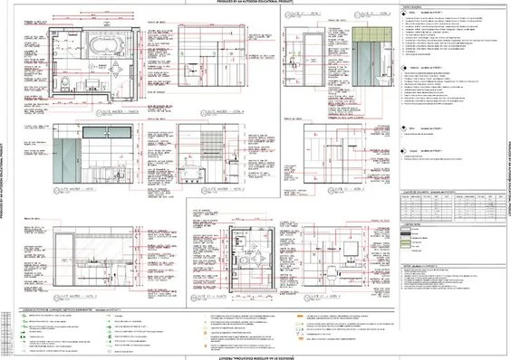
Note: blurred for privacy reasons
Coding Systems
When setting out fixtures related to plumbing, doors & windows, and electrics, the contractor needs to know precisely what fitting is being fitted where. Architects approach this through a coding system which will differ depending on the practice but the general idea is that these codes are placed on drawings and reference an exact fitting listed in a schedule.
For example,
RAD-01-01 suggests the first radiator on the ground floor that’s listed first in the schedule. The schedule will have corresponding information like technical specifications, size, colour, etc. This information is inconvenient to put on the main drawing as it will crowd it up amongst the other annotations and could bombard the client when they only want to see a design change. The same can be done with taps, shower trays, light switches, etc, and only so much would be able to fit on a page before you lose the drawing you began with.
Note: blurred for privacy reasons
Keys are Extremely Important in Construction
Generally, when you’re referring to a ‘key’ in an architectural drawing at University it tends to suggest the program of your proposal. It could be a numbered key or a list of colour coding whereas, in construction drawings, there are a plethora of keys needed for all sorts of information and program is only one of many.
The Types of Drawings
No, we are not referring to sections, plans or elevations. We are talking about GAs, ADs, CDs, SKs & SCs which stand for ‘General Arrangement, ‘Assembly Drawings’, ‘Component Drawings’, ‘Sketches’ and last but not least ‘Schedules’ respectively.
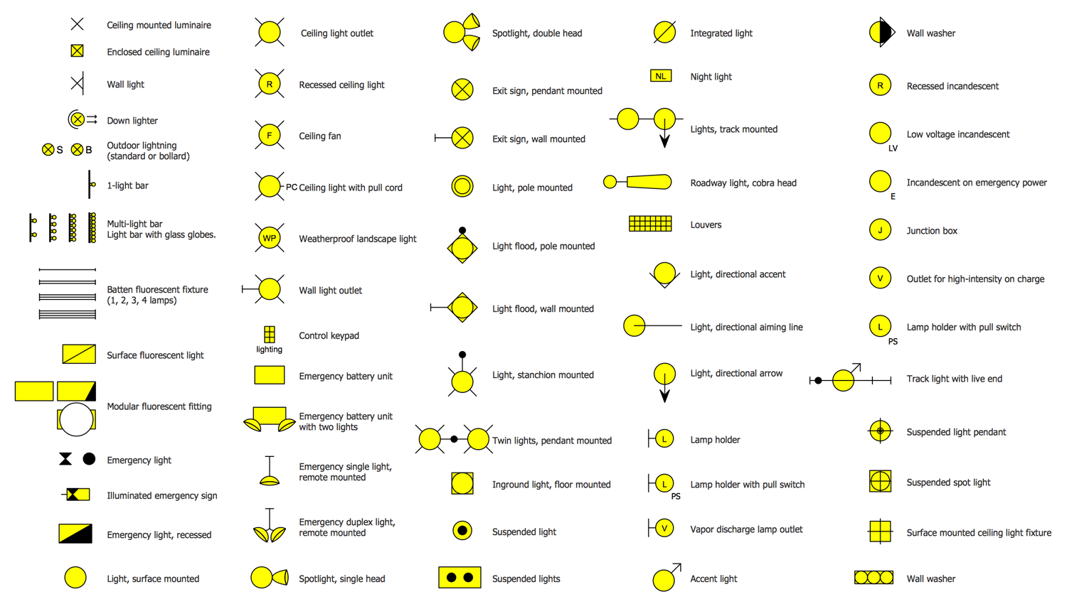
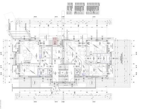
General arrangement drawings give the contractor about elements that affect the proposal on an entire level. Your plans, sections and elevations would be included as well as additions such as lighting arrangements, electrical arrangements, internal insulation diagrams, heating plans, fire strategy drawings, + more. In the planning stages, the existing drawings that fall within this category would also be regarded as a part of your GA drawings.
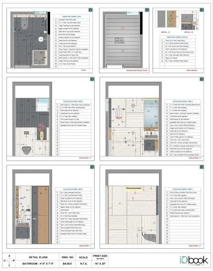
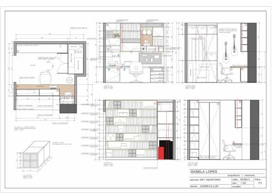
Assembly drawings zoom into each room and are made up of the elevation drawings of the room as well as a larger-scale plan. Each room would have its own AD and is used to understand in better detail for setting out fixtures, floor/wall/ceiling finishes, room heights, window heights, any potential joinery and more. It’s the next level to detail once you get a grasp of the entire project through the GA drawings.
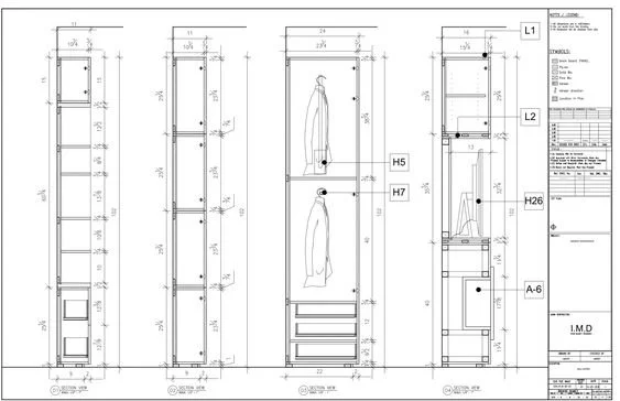
Component drawings are quite important when understanding and putting things together. Contractors use component drawings to actually, well… construct each component. This can vary from joinery drawings to party wall details approved by party wall surveyors and any typical details like roof, ceiling, floor or wall build-ups that the practice uses throughout projects and the niche detail drawings when you have the one-off awkward interface in the project. Alongside these, contractors will also refer to structural engineer drawings and any other drawings containing technical design information.
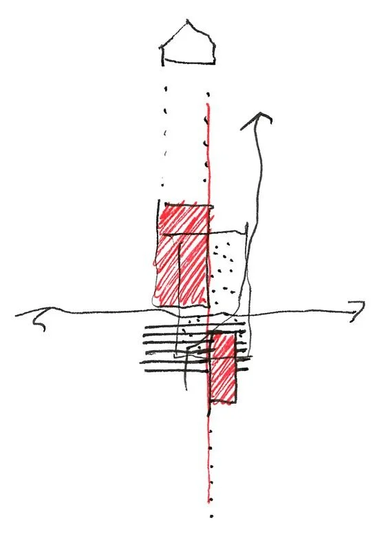
Sketches are the least mentally draining to understand. They are quite simply sketches by the architect that tend to not be in scale or CAD drawn to further aid the contractor or client with construction or design ideas.
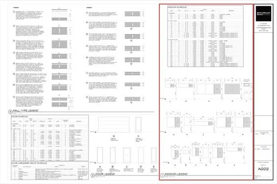
Finally, ‘schedules’ are where all the technical specifications of all fittings are documented which contractors will see in the main drawings the codes referenced. Information on these will help plumbers, electricians and other sub-contractor installers since the correct wiring and piping need to be laid out. Usually, information such as colour, finish, supplier, tech spec sheets, quantity, price, dimensions, and the associated room can be found in these documents in the form of a list or table. That would depend on the practice.
It is been nearly a year in practice for both of us and we have really come to terms with how different architecture school is to working in the architecture field. If you want to learn more about these differences and get an insight into the life of two Part 1 Architectural Assistants in London, all you have to do is keep posted over on our Instagram where we share all the things we get up to as well as our future journeys in this field.
See you there!